Pack Description
1-3
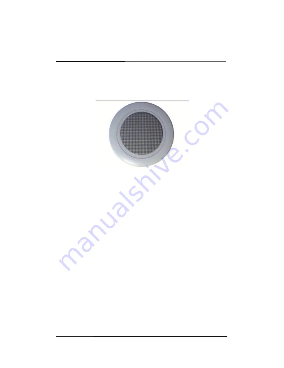
100V Speakers
General Description
6W/100V speaker. Wideband, it has an excellent audio
quality. Its small diameter provides a discrete
installation in the ceiling.
Page 1: ...60W Sound Pack Installation AXCITY ZAC des Hauts de Wissous Air Park de Paris Bâtiment le Cormoran 3 rue Jeanne Garnerin 91320 Wissous France ASBSOP0201 n 1 2012 ...
Page 2: ...Pack Description Box Contents 1 1 60W Amplifier 1 2 100V Speakers 1 3 Speaker Cable 1 4 Chapter 2 Pack Implementation Step 1 Speakers Connection 2 5 Step 2 AM FM Antenna Connection 2 8 Step 3 Power Cord Connection 2 9 Step 4 Amplifier Start up 2 10 ...
Page 3: ...Chapter 3 Quick Troubleshooting 60W Pack 3 12 Appendix A Technical Data Sheets Appendix B Associated Documents ...
Page 4: ...llowing items 1 60W amplifier with USB CD Tuner 6 6W 100V speakers 1 AM FM antenna 1 power cord 100 meters of speaker cable If any of these are incorrect missing or damaged contact your Axcity dealer Keep the original box and packing materials in case the product needs to be sent back for repair ...
Page 5: ... with an AM FM tuner and a CD MP3 USB player The volume control covers all areas It can also be used at full power in single zone mode Its LCD screen provides the view of the radio station or CD USB title playing Tuning radio stastion is accomplished automatically using the scan function ...
Page 6: ...Pack Description 1 3 100V Speakers General Description 6W 100V speaker Wideband it has an excellent audio quality Its small diameter provides a discrete installation in the ceiling ...
Page 7: ...Pack Description 1 4 Speaker Cable General Description Flat loudspeaker cable dedicated to the 100 volt line Suitable for all types of sound systems it can be used both in fixed and mobile installations ...
Page 8: ...ion Step 1 Connection of the speakers to the amplifier Beforehand you must connect the speakers to speaker cables Then connect the speaker cable s to the amplifier General view of the rear of the amplifier Start by stripping each conductors about 5 mm ...
Page 9: ...Pack Implementation 2 6 Fig 1 Unscrew the COM terminal on the right Insert the black conductors into the space between the connection plate and the fixed terminal Screw up the COM terminal ...
Page 10: ...nsert the red conductors into the SP1 terminal corresponding to the 1st zone The SP2 and SP3 terminals correspond to zones 2 and 3 Note 1 wired zone 60W output power 2 wired zones 20W output power 3 wired zones 20W output power ...
Page 11: ...Pack Implementation 2 8 Step 2 Connection of the AM FM antenna to the amplifier fig 2 Connect a conductor to the GND terminal Connect the other conductor to the 75Ω terminal ...
Page 12: ...Pack Implementation 2 9 Step 3 Connection of the power cord to the amplifier fig 3 Plug the power cord into the outlet provided for that purpose Turn the amplifier on ...
Page 13: ...Pack Implementation 2 10 Step 4 Starting the Amplifier Press the POWER button after checking that the MASTER button is on 0 Select the zone s for distribution ...
Page 14: ...2 11 The red LED lights to indicate the amplifier is powered up In order to access to the AM FM tuner as well as the CD MP3 and USB player press the sound volume button Select the desired source To turn off press and hold ...
Page 15: ... unit is functioning properly Check that the speakers are properly connected to each other and to the amplifier To do so press the CHIME button If sound comes out of the speakers that means the 100V line is working properly Therefore the problem must have a different source If no sound comes out of the speakers check that the amp s master button is pressed ...
Page 16: ...60W 3 x 20W Bandwidth 80 Hz 15 kHz Signal noise ratio MIC 70 dB Signal noise ratio LINE 60 dB Distortion Ratio 1 1 kHz MIC Inputs Symmetric 3 mV LINE inputs 300 mV PHONE Inputs 2 40 mV Speaker Outputs 70 100 4 and 8 Ohm Power Supply 240 VAC 50 60 Hz 24 VDC Dimensions 420 mm x 110 mm x 320 mm Weight 10 kg ...
Page 17: ... 3 Frequency Response 120 Hz 20 kHz Rated Power 6 W RMS Nominal SPL 1W 1M 91 dB Max nominal SPL 6W 1M 99 dB Directive 89 Power selection by wiring 3 6 6W 8Ω Mounting Type Ceiling Colour White RAL 9016 Cross section Ø 95 mm Dimensions 103 mm x 80 mm Weight 0 22 kg ...
Page 18: ...rical shock hazards do not remove the cover No maintenance of internal parts must be done by users contact qualified personnel If necessary N NO OT TI IC CE ES S In order to avoid fire and electric shock hazards do not expose this product to rain or moisture ...
Page 19: ...rovides links to reference documents that can help you to understand better the technologies used for your Axcity product Documents Link Amplifier Technical Data Sheet Amplifier User Manual Speaker Technical Data Sheet www axcity fr www axcity fr www axcity fr ...