


A member of Neumo Ehrenberg Group
OPERATING / INSTALLATION INSTRUCTIONS
(Translation)
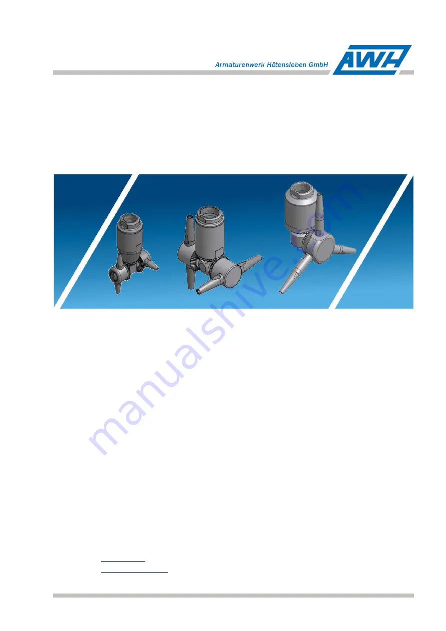
Container cleaning Device
Jet Cleaner TANKO
®
JM100/500/800
Armaturenwerk Hötensleben GmbH
Schulstr. 5-6
39393 Hötensleben, Germany
Telephone: +49 39405 92-0
Fax:
+49 39405 92-111
E-mail:
Homepage:
ID no.: 664BAJM0000EN
–
2016/12 Rev. 1