13
S
T
E
P
2
0
S
F
3
X
8
S
S
3
X
4
P
1
2
X
S
F
3
X
8
M
3
x8
Fl
a
t
h
ead Screw
x
4
SS
3
X
4
M3x
4
Set Screw x4
P
1
2
X
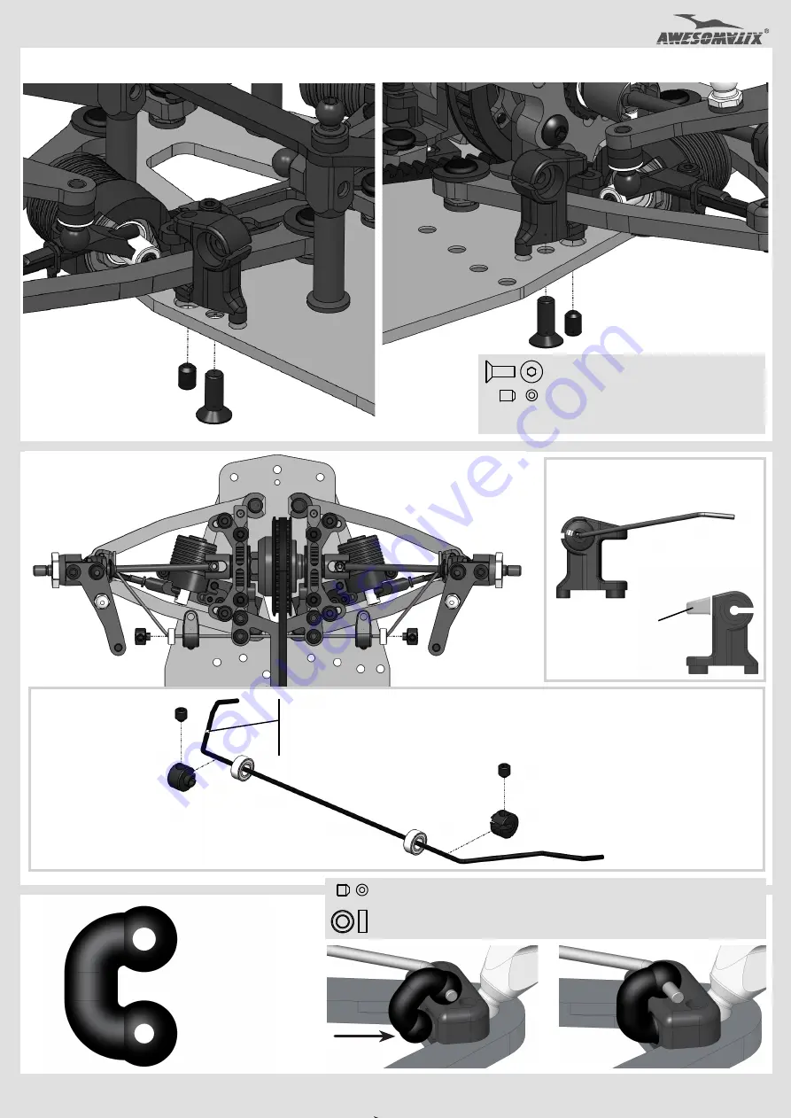
Sway Bar Holder
x
4
S
F
3
X
8
S
S
3
X
4
P
1
2
X
I
nstall four
P12
X
Sway Bar Holders.
S
T
E
P
2
2
P05
U
se b
igger
h
ole
f
or
S
B
1
2
S
w
a
y
Bar
s
.
Use s
m
aller
h
ole
f
or
S
B
1
0
an
d
S
B
1
1
S
w
a
y
Bar
s
.
snap
S
T
E
P
2
1
S
W
B1
0
...
S
W
B1
2
A
ttention
!
T
h
e
d
eflected
t
i
p
s
of
S
way Bar
sh
o
u
ld
b
e
d
i
rected
dow
n
ward
s.
A
T1
4
2
S
W
B1
0
...
S
W
B1
2
N
ot
e
:
S
W
B
12
- t
wo
strip
s
S
W
B
11
- o
ne
strip
S
W
B
1
0
- n
o
strip
A
T1
4
2
S
S
3X3
S
S
3X3
B
6
3S
S
B
6
3S
S
N
o
te
:
D
o
n
’
t t
i
g
h
t
e
n
SS
3
X
3
Set Screws at this stage.
S
S
3X
3
M3x
3
Set
Screw
x4
B
6
3
SS
M
R
6
3
ZZ Bearing x4
S
W
B
1
0
....
SWB1
2
Sway Bar
x
2
P
0
5
Sway Bar Joint
x4
AT1
42
Swa
y
Bar S
to
pper
x4
snap
I
nstall the front
S
way Bar
and the rear Sway Bar.
T
h
is part of
P
1
2
X
ca
n
b
e c
u
tte
d
i
f
higher ro
ll
ce
n
ters
wi
ll
b
e
used.


