1-1. Table of Contents
1. General Information...........................................................................
1-1. Table of Contents
1-3. Important Notice
1
Chapter 1: General Information
1
3
1-2. General Guidelines
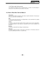
1-4. How to Read this Service Manual
3
6
....................................................................................
Service Manual
Model No.:
- 01 -
3. Location of Controls and Components...........................................
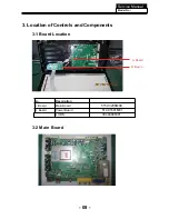
3-1. Board Location
3-2. Main Board & AV Board
3-3. Power Board
3-4. LCD Panel
4. Disassemble and Assemble
..........................................................
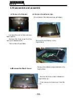
4-1 Remove the Pedestal
6
8
8
8
8
11
12
15
15
4-2 Remove the Back Cover
15
4-3 Remove the Adhesive Tape
15
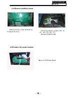
4-4 Remove the Power Module
16
4-5 Remove the Main Board
16
4-6 Remove the Speaker
17
4-7 Remove the Remote Control Board
17
5. Installation Instructions..
…....………………...........………….........
18
5-1 External Equipment Connections
18
5-2 HDMI Connections
21
6. Operation Instructions....
…....………………...........………….........
24
6-1 Front Panel Controls
6-2 Back Panel Controls
6-3 Universal Remote Control
24
24
25
7. Electrical Parts
…....………………...........………….........................
26
7-1. Block Diagram
8-1. How to enter into the factory model
8-2. How to update software
7-2. Circuit Diagram
7-3. Wiring Connection Diagram
26
27
44
35
45
8. Measurements and Adjustments
........…………............................
39
Summary of Contents for MSDV1636-O3
Page 13: ...3 4 LED Panel 12 Service Manual Model No 316156WB111 CLAA156WB 11A ...
Page 28: ...7 Electrical parts 7 1 Block diagram Service Manual Model No 26 06 ...
Page 48: ...Service Manual Model No 46 9 Trouble shooting 9 1 Simple check ...
Page 50: ...Service Manual Model No 48 3 Panel display abnormally connector j20 is at normal level ...
Page 54: ...Service Manual Model No 52 7 PC no picture or picture abnormal ...
Page 55: ...Service Manual Model No 8 YPBPR AV SCART no picture or picture abnormal Check Y 53 ...


