Hybrid DVR
(Digital Video Recorder)
Quick Start Guide
1. Notes
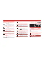
4. Rear Panel Instructions
6. Login
2. Packing Check
Please inspect the device and accessories after purchasing the device. If there are
any visible damages, shortages or defects, please contact your dealer or distributor
immediately.
7. Analog Camera Connection
8. Network Configuration & Add IP Camera
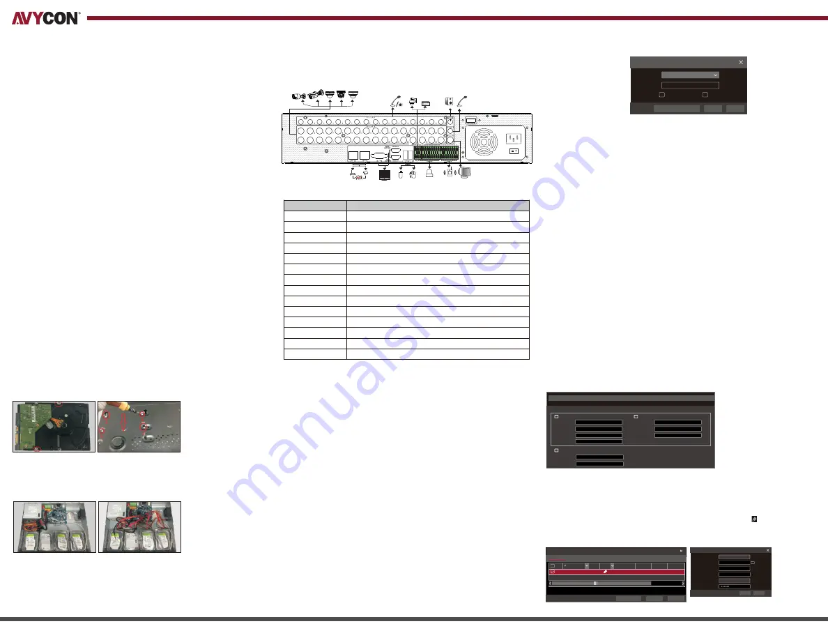
3. HDD Installation
5. Startup & Shutdown
This model of recorder supports 8 internal SATA hard drives. The following pictures
and diagrams of the HDD installation are for reference only and there might be slight
differences in the actual hardware received. Please make sure that the device is
powered off before the installation.
①
Remove the chassis cover and loosen the screws to remove the two HDD
mounting bars.
②
Align the HDDs to be installed to their proper mounting holes and secure the
HDDs onto the mounting bar with included screws.
Startup
①
Connect recorder to monitor with VGA or HDMI cable and power on device.
②
The device will boot and the power indicator will display blue.
③
After completely booting, a Startup Wizard should appear on the screen.
Shutdown
①
Click on “Start” button in lower-left corner of the screen and then select
“Shutdown” icon. This will bring up a shutdown window.
②
From within this new window, choose “Shutdown”. After recorder has completely
shut down, you can disconnect the power.
First connect the camera to the DVR. Then go to
Start>Settings>Camera>Manage
Camera>Camera Signal
to checkmark the video mode. The actual signals input shall
correspond to the video mode. Please refer to User Manual for details.
After you finish adding your analog cameras, you can see their live video streams
through the monitor connected to the DVR. The following instructions will mainly
introduce how to add the IP cameras via LAN/WAN.
LAN
①
Most networks will be configured for assigning an IP address automatically through
the router. After connecting this recorder to your network, navigate to
Start>Settings>Network>TCP/IP. If using DHCP, make sure that the option of
“Obtain an IPv4 address automatically” is selected. For manual IP address, make
sure to uncheck the “Obtain an IPv4 address automatically” option and enter
in the proper Address, Subnet Mask and Gateway information.
④
Navigate to Start>Settings>Camera>Add Camera. The DVR will search your local
network for cameras and list them. AVYCON and ONVIF cameras will be supported
automatically. If any AVYCON IP cameras are found, but do not have an IP address
that matches your local network, you can click on the Edit button for each camera
and modify the IP address directly from the DVR.
③
Re-install the two HDD mounting bars with HDDs attached and make sure to
tighten mounting bar screws.
④
Connect power and data cables to all HDDs installed.
⑤
Replace chassis cover and make sure to secure it with the included screws.
Tip: Before securing chassis cover, double-check all power and data connections
to HDDs and mainboard.
Diagram of rear panels below are for reference only.
②
To change the ports used by
the recorder, navigate to
Start
>Settings >Network >Port
. You
can enter a different HTTP port
(default value is 80) and Server
port (default port is 6036).
③
Click “Apply” to save the
settings.
Please read these instructions carefully and store them in a cool dry place for future reference. All the examples
and pictures used here are for reference only. There may be several technically incorrect diagrams or printing
errors in this manual. Any updated information will be added to successive versions of this manual. The
contents of this manual are subject to change without notice.
- Please read these instructions carefully and store them in a cool dry place for future reference
- All the examples and pictures used here are for reference only
- The contents of this manual are subject to change without notice.
- This device should be operated only from the type of power source indicated on the labeling.
Please verify that the voltage used matches what is indicated on the labeling.
IP Address Settings
Obtain an IPv4 address automatically
Obtain an IPv6 address automatically
Ethernet Port 1 ( Online )
Obatin DNS server address automatically
Address
Address
Preferred DNS
192 . 168 . 1 . 2
0 . 0 . 0 . 0
0
192 . 168 . 1 . 1
1500
192 . 168 . 1 . 1
0 . 0 . 0 . 0
Subnet Mask
Mask Length
Alternate DNS
Gateway
Gateway
MTU
Username
Password
admin
Login
Enter Password
Display Password
Log In Automatically
Login
Edit
S
ecurity
Q
uestion
Cancel
The default username is
admin
and the default password is
123456
. You must configure
the wizard if you start the DVR for the first time and you may change the password
when you configure the wizard for the first time. You can skip the settings of wizard next
time. Click “Start” and select “Login”. This will take you to see a login box.
Enter default username and password you set and you can see the live image.
4.0.0.1.beta1
Version
80
No.
Address
Edit
Port
Protocol
Model
Subnet Mask
1
192.168.2.45
XXX
XXX
255
.
255
.
255
.
0
Quickly Add
Manually Add
Add
Camera
Selected: 1/1
Add
Default Password
Remain Bandwidth: 10 / 10 Mb
Cancel
Mac Address
Address
Sync to IPC
Edit IP
192
.
168
.
1
. 45
255
.
255
.
255
. 0
admin
192
.
168
.
1
. 1
Subnet Mask
Username
Gateway
Password
OK
Cancel
CE :98 :23 :75 :35 :22
VGA
Connect to monitor
Connect to high definition display device
Network Port
Connect to USB storage debice or USB mouse
Alarm input for connecting sensor
Relay output; connect to external alarm
Ground
Connect to speed dome. Y is TX +,z is TX -
Connect to keyboard. A is TX +, B is TX -
Audio ouput
Audio input
Connect to HDD with e-SATA interface
HDMI 1
LAN
USB
ALARM IN
ALARM OUT
GND
P/Z
K/B
AUDIO OUT
AUDIO IN
e-SATA
Name
Description
Connectors for Video input
VIDEO IN
Connect to high definition display device
HDMI 2