


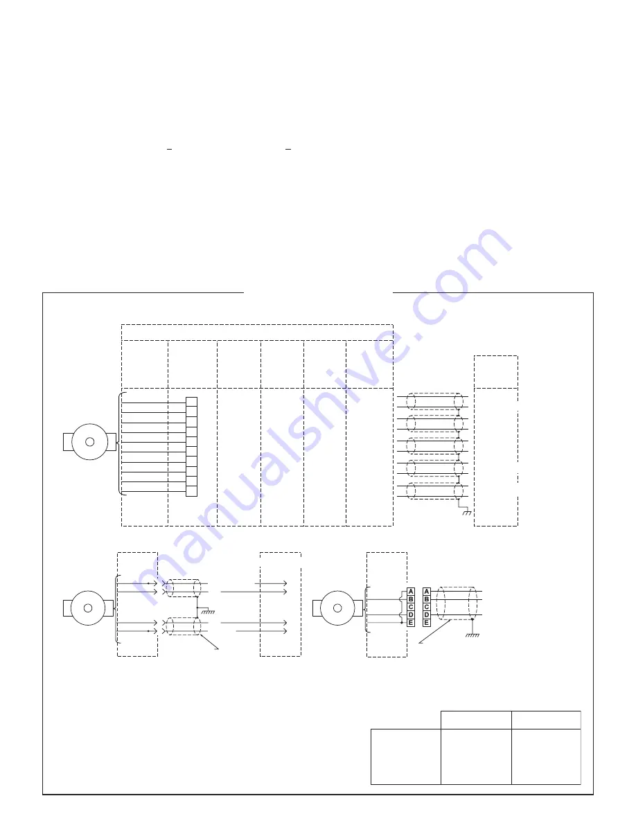
OUTPUT
BOX
(USE CONNECTOR OPTIONS “E” & “F”
FOR M737A REPLACEMENTS)
+5 TO +24 VOLTS
*
ØB
*
(SEE LINE DRIVER OPTIONS)
ØA
COMMON
GROUND
CABLE BELDEN 8723
OR EQUIVALENT
RED
BLUE
GREEN
BLACK
B
C
E
A
E
D
A
F
SINGLE ENDED TWO PHASE WIRING APPLICATIONS
CABLE BELDEN 8771
OR EQUIVALENT
COMMON
+5 TO +24 VOLTS
*
SIGNAL
GROUND
OUTPUT
BOX
(USE CONNECTOR OPTIONS “H” & “J”
FOR M727A REPLACEMENTS)
RED
GREEN
BLACK
SINGLE ENDED SINGLE PHASE WIRING APPLICATIONS
*
(SEE LINE DRIVER OPTIONS)
OPTION D
M940 REPLACEMENT
OPTION
“W” & “N”
REF
SIGNAL
OPTION
“A” “B” “C”
“K” “L” “M”
OPTION
“A” “B” “C”
“K” “L” “M”
With Mod.
030
OPTION
“P” “V”
“X” & “Z”
OPTION
“T”
OPTION
“R” & “S”
SIGNAL CODING TABLE
BLACK
RED
GREEN
YELLOW
BLUE
GRAY
ORANGE
WHITE
BROWN
VIOLET
F
D
A
H
B
J
C
K
not used
not used
F
D
A
H
B
I
C
J
1
2
3
4
5
6
7
8
9
10
1
6
2
7
3
8
4
9
5
10
not used
not used
COM
+V
ØA
ØA
ØB
ØB
Z
Z
C
C
DIFFERENTIAL TWO PHASE WIRING APPLICATIONS
A
B
D
G
E
H
C
I
F
J
+5 TO +24 VOLTS
*
= MARKER
= ØA
∏
4
*
(SEE LINE DRIVER OPTIONS)
–
–
–
–
WIRING DIAGRAMS
NOTES:
Marker output for connector options “E” & “F” - Pin “D”
Marker output for connector options “H” & “J ” - Pin “C”
Avtron standard warranty applies. Copies available upon request.
Specifications subject to change without notice.
BELDEN
2 PAIR
3 PAIR
4 PAIR
6 PAIR
TYPICAL WIRE SELECTION CHART
for 18 AWG, multiple pair, individually shielded
9368
9369
9388
9389
6062C
6063C
6064C
6066C
ALPHA
For bidirectional operation of the encoder, proper phasing of the two
output channels is important. Phase A channel leads phase B channel
for clockwise shaft rotation as viewed from the anti-drive or accessory
end of the motor (M3 mounting end).
CORRECTIVE ACTION FOR PHASE REVERSAL
1) Remove Power.
2) Exchange wires on cable, either at encoder cable end, or at
speed controller end (but not both).
a) Single Ended 2 Phase Wiring (see wiring diagram)
Exchange A and B at the use end of the wires.
b) Differential 2 Phase Wiring (see wiring diagram)
Exchange either A with A in the phase A pair OR B with B
in the phase B pair but NOT both.
3) Apply Power.
4) Verify encoder feedback is correct, using hand rotation of
shaft, or jog mode of the speed controller.
Interconnecting cables specified in the wire selection chart are based
on typical applications. Refer to the system drawing for specific cable
requirements where applicable.
Physical properties of cable such as abrasion, temperature, tensile
strength, solvents, etc., are dictated by the specific application.
General electrical requirements are: stranded copper, 22 thru 16
gauge (Industrial EPIC Connector options can use 14 AWG), each wire
pair individually shielded with braid or foil with drain wire, 0.05 uF
maximum total mutual or direct capacitance, outer sheath insulator,
1,000 ft. max. See Wire Selection Chart for some suggested cables.
NOTE
When using the industrial connector (“G”, “P”, “V”, “X”,
or “Z” options), the minimum wire size is 20 gage, and
20 gage (only) wire ends must be tinned with solder
before connection at the
screw terminals.