HS6A
1
8 9 0 1 E . P L E A S A N T VA L L E Y R O A D • I N D E P E N D E N C E , O H I O 4 4 1 3 1 - 5 5 0 8
T E L E P H O N E : ( 1 ) 2 1 6 - 6 4 2 - 1 2 3 0 • FA X : ( 1 ) 2 1 6 - 6 4 2 - 6 0 3 7
E - M A I L : t a c h s @ n i d e c - a v t r o n . c o m • W E B : w w w. a v t r o n e n c o d e r s . c o m
Nidec-Avtron Makes the Most Reliable Encoders in the World
Encoder Instructions
MODEL
HS6A
HOLLOW SHAFT 6mm-15mm BORE
DESCRIPTION
The Avtron Model HS6A is a light mill duty absolute encoder. It
expresses the position of rotation as an output message or value.
HS6A can measure a single turn of rotation or multiple rotations. The
HS6A measures the shaft rotation and position without the need for
external power or internal batteries or capacitors through its internal
gearbox system. The HS6A operates down to zero speed and can be
used for both control and instrumentation applications.
CAUTION
Do not utilize HS6A in hazardous locations which
require ATEX, UL, CUL, CSA, or other explosion protection
certification. HS6A is not certified for hazardous
locations.
The HS6A is designed for direct mounting on shafts and utilizes a
tether mount to secure the housing.
The HS6A features an interchangable set of sizing inserts to allow
the same unit to fit shafts over the full size range, 6-15mm. Note
that the optional thru-shaft 12mm unit can also be resized 6-12mm
using a different set of sizing inserts.
The HS6A uses optical sensors; to protect the optical sensors and
bearing systems HS6A features extensive seal systems. (Option “X”
unsealed is only available/standard on 12mm thru-shaft).
SAFETY
The HS6A is not considered as a safety device and is not suitable for
connection into a safety system.
CAUTION
Be careful not to damage clamping fingers of hollow
shaft during handling. Do not tighten clamping collar
before installation onto motor shaft.
WARNING
Installation should be performed only by qualified
personnel. Safety precautions must be taken to ensure
machinery cannot rotate and all sources of power are
removed during installation.
INSTALLATION
Refer to the back page of these instructions for outline and mounting
dimensions.
Equipment needed for installation
Supplied:
HS6A Encoder
Standard flat metal tether (2.48” [63mm] BC)
Optional:
Mating plugs
Mating cable assemblies
Not Supplied:
Hex Wrenches
Dial Indicator Gauge
Caliper Gauge
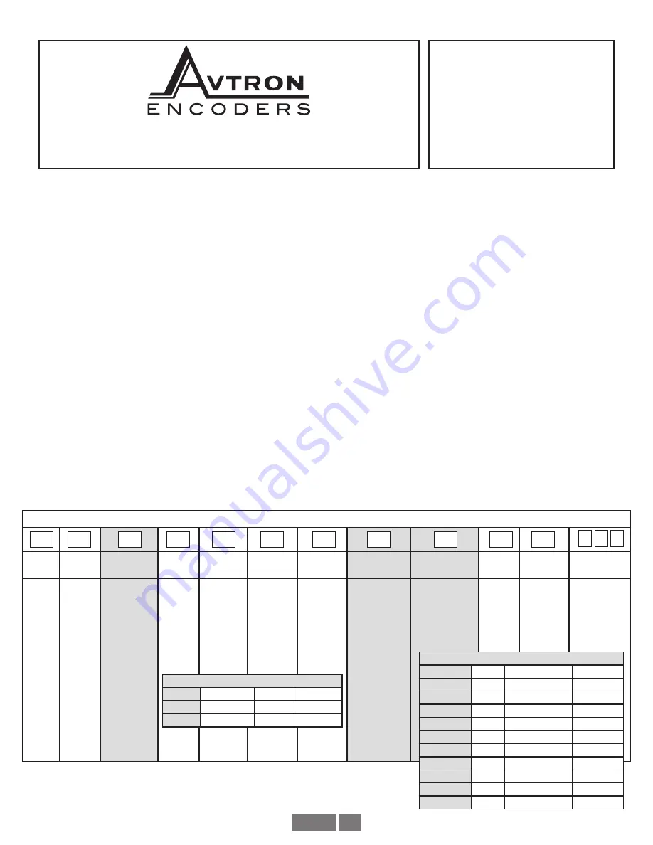
HS6A PART NUMBERS AND AVAILABLE OPTIONS
Model Sensor
Bus
Style
Shaft
Size
Turns/
bits
PPR/bits
per turn
Connector
Mounting
Output
IP
Rating
Special
Option
HS6A
A-
Optical
C-
CANOpen
D-
DeviceNet
F-
CANSafe
K-
POWERLINK
L-
Parallel
M-
ModbusTCP
Ethernet
N-
Profinet IO
P-
Profibus DP
R-
Ethernet/IP
S-
SSI
1-
58mm
housing
L-
6mm
M-
8mm
N-
10mm
P-
12mm
R-
15mm
(EOS only)
Z-
All metric
sizes
X-
0/0- single
turn
2-
4096/12
4-
16384/14
2-
4096/12
3-
8192/13
4-
16384/14
6-
65536/16
A-
1xM12/5 pin
B-
2xM12/5 pin
C-
3xM12 4/4/5
or 4/4/4 pins
D-
2xM12/4/5 pin
E-
M12/8 pin
F-
M23/12 pin
G-
M27/26pin
J-
2x cable entry
K-
3x cable entry
M-
M23/8pin
Hengstler
N-
M23/8pin
Stegmann
Q-
M23/8pin
Kubler
W-
Cable, 1m
E-
EOS only
U-
EOS or Thru
(12mm SSI only)
1-
Binary
2-
Gray
X-
None, IP54
A-
IP66 shaft
seals
S-
IP66 seals,
stainless
housing
000-
none
9xx-
special
cable
length
xx=length
0.3m/ft
MOUNTING COMPATIBILITY
Housing
Bore Size
Mounting IP/Sealing
1
M, N, P, R, Z E
A, S
1
P
U
X
STANDARD CONNECTORS & OUTPUT FORMATS
Bus
Code
Connectors
Output
CANOpen
C
A, B, C, J, K, W
1
DeviceNet
D
A, W
1
CANSafe
F
K
1
POWERLINK
K
C
1
Parallel
L
G, W
1, 2
ModbusTCP
M
D
1
Profinet
N
C
1
Profibus DP
P
C, J, K
1
EtherNet/IP
R
C
1
SSI
S
E, F, W
1, 2


