background image

8

        Digital Desktop System Installer/User Guide

4.

Remove the computer cover to access the interface cards.

5.

If applicable, remove the current video and audio interface cards from the computer. 

To configure the PCI Add In Card:

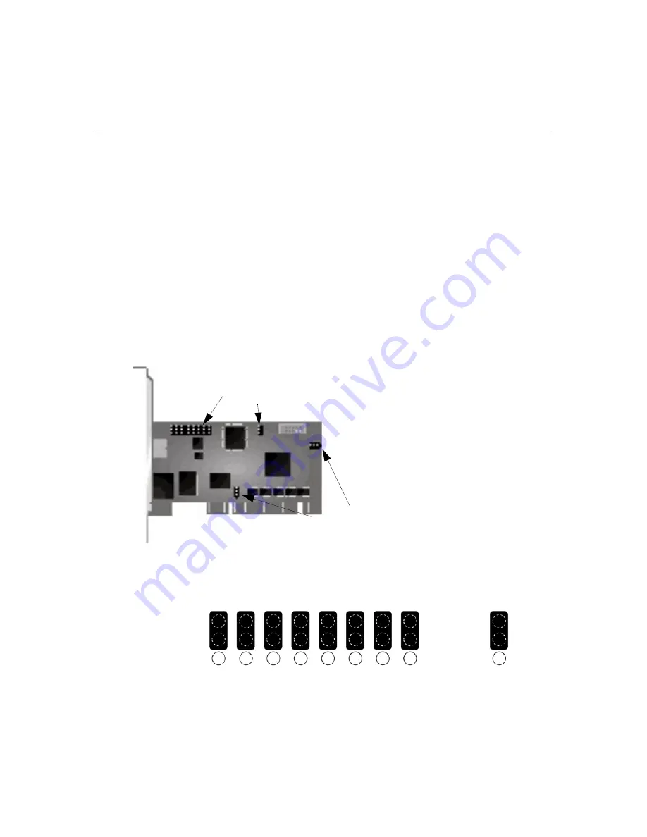
Several jumpers and two sets of connectors on the PCI Add In Card are used to configure your 
Digital Desktop System. An optional short bracket is also provided to accommodate a low profile 
PCI form factor. 

1.

Determine which PCI slot form factor is available for you to install the PCI Add In Card. The 
PCI Add In Card is shipped with a tall bracket mounted for use with standard PCI slots.           
A short bracket is provided for low profile PCI slots. You may need to change the bracket 
before installing the PCI Add In Card.

2.

Configure the PCI device jumpers on the PCI Add In Card. These jumpers allow you to selec-
tively disable certain components of your Digital Desktop System. The factory default is set 
with all components enabled. Figure 2.3 identifies the enable/disable positions for each 
jumper. Table 2.1 identifies which PCI devices are controlled by each jumper.

Figure 2.2: PCI Add In Card Jumpers

Figure 2.3: PCI Add In Card Device Jumper Configuration

 Device Jumpers

Auxiliary Power Jumpers

J1

J2

J3

J4

J5

J6

J7

J8

J9

1

2

3

Enable

Disable

Summary of Contents for C Series

Page 1: ...Huntsville Alabama 35805 6201 USA Tel 1 256 430 4000 Fax 1 256 430 4031 590 422 001A Avocent International Ltd Avocent House Shannon Free Zone Shannon County Clare Ireland Tel 353 61 715 292 Fax 353 61 471 871 Email Techsupport Shannon avocent com www avocent com support Digital Desktop System ...

Page 2: ...ntenance servicing instructions in the literature accompanying the appliance DANGEROUS VOLTAGE This symbol is intended to alert the user to the presence of uninsulated dangerous voltage within the product s enclosure that may be of sufficient magnitude to constitute a risk of electric shock to persons ...

Page 3: ...cent the Avocent logo The Power of Being There and Reclaim Your Desktops are registered trademarks of Avocent Corporation or its affiliates All other marks are the property of their respective owners 2005 Avocent Corporation All rights reserved 590 422 001A ...

Page 4: ...en the equipment is operated in a commercial environment This equipment generates uses and can radiate radio frequency energy and if not installed and used in accordance with the instruction manual may cause harmful interference to radio communications Operation of this equipment in a residential area is likely to cause harmful interference in which case the user will be required to correct the in...

Page 5: ...sion Detect option 3 Loose Link protection 3 Lower Total Cost of Ownership TCO 3 Safety Precautions 3 Chapter 2 Installation 5 Getting Started 5 Supplied with the Desktop Appliance 5 Supplied with the PCI Add In Card 5 Additional items needed 5 Recommended configuration 5 Cable network specifications 6 Remote Power Control option 6 Installing the Digital Desktop System 7 Configuring the Desktop Ap...

Page 6: ...Overview 17 LED identification 17 LED Definitions 18 Remote Power Control 19 Using the Hotkey Feature 20 Appendices 23 Appendix A Troubleshooting 23 Appendix B UTP Cabling 26 Appendix C Technical Specifications 29 Appendix D Technical Support 30 Index 31 TABLE OF CONTENTS ...

Page 7: ...umpers 10 Figure 2 5 Installing the PCI Add In Card 11 Figure 2 6 Connecting Cables to the PCI Add In Card 11 Figure 2 7 Video and FLASH Jumpers 12 Figure 2 8 Installing a Third Party PCI Add In Card 13 Figure 2 9 Desktop Appliance Right Side View 14 Figure 2 10 Desktop Appliance Rear View 15 Figure 3 1 LED Identification Desktop Appliance Right Side 17 Figure 3 2 LED Identification PCI Add In Car...

Page 8: ...vi Digital Desktop System Installer User Guide ...

Page 9: ...er FLASH Types 12 Table 3 1 Hotkey Command Table 21 Table A 1 Desktop Appliance PCI Add In Card Troubleshooting 23 Table B 1 Digital Desktop System Wiring Standards 26 Table B 2 Link Distances 27 Table C 1 Digital Desktop System Technical Specifications 29 LIST OF TABLES ...

Page 10: ...viii Digital Desktop System Installer User Guide ...

Page 11: ...rd interconnecting link and a Desktop Appliance Figure 1 1 This provides centralized control of PC resources NOTE The information contained in this guide is for use with all C Series Digital Desktop Systems However where information pertains only to specific models the model number is noted Figure 1 1 Digital Desktop Basic System Rack Mounted PCs and Blades Gigabit Ethernet Switch Desktop Applianc...

Page 12: ...jumper settings on the PCI Add In Card or using the DWorks Administration Utility On board video support The Desktop Appliance is supplied with a built in video adaptor providing digital resolutions of up to 1280 x 1024 at 60 Hz or analog resolutions of up to 2048 x 1536 at 60 Hz Integrating the video adaptor also reduces video degradation to levels beneath user detection This may also be accompli...

Page 13: ...r away from the user frees up valuable office space and reduces desktop power and heating ventilation and air conditioning HVAC requirements Safety Precautions To avoid potential video and or keyboard problems when using Avocent products If the building has 3 phase AC power ensure that the computer and monitor are on the same phase For best results they should be on the same circuit To avoid poten...

Page 14: ...4 Digital Desktop System Installer User Guide ...

Page 15: ...nal items needed Either CAT 5 cable DDC20xx models or standard multimode fiber optic cable DDC21xx models is required for correct operation of the Digital Desktop System This cabling is user supplied and commonly found in pre existing network installations If you are missing any of the listed items from your shipment contact Avocent Technical Support For more information see Appendix D on page 30 ...

Page 16: ...vers should be retained and reinstalled whenever the fiber cable is removed or if the product is packaged for storage or shipment The link cabling between the remote Desktop Appliance and the computer must be either a point to point connection or connected through a 1 Gb Ethernet switch If it is a point to point connection no other active devices such as routers or hubs may be present in the link ...

Page 17: ...edures outline how to successfully install your PCI Add In Card and Desktop Appliance Figure 2 1 Basic Digital Desktop System Configuration CAUTION To reduce the risk of electric shock or damage to your equipment Disconnect the power from the unit by unplugging the power cord from either the electrical outlet or the unit To prepare your computer for installation 1 If your computer has integrated v...

Page 18: ... In Card is shipped with a tall bracket mounted for use with standard PCI slots A short bracket is provided for low profile PCI slots You may need to change the bracket before installing the PCI Add In Card 2 Configure the PCI device jumpers on the PCI Add In Card These jumpers allow you to selec tively disable certain components of your Digital Desktop System The factory default is set with all c...

Page 19: ... Add In Card or Desktop Appliance using the PCI device s Ethernet address over a switched network 3 If you purchased the RPC option for your Digital Desktop System please refer to the instruc tions provided with the cable specific to your computer Figure 2 4 identifies the jumpers used to select the appropriate auxiliary power setting The factory default setting is for use of 3 3 V auxiliary power...

Page 20: ...ve the instructions provided with your RPC cable or if you have changed the type of computer you will be using with your Digital Desktop System contact Avocent Technical Support for further information J17 J14 J14 J17 J17 5V WOL External 5V PCI 3 3V Aux Default Ext Ext Ext Aux Aux Aux 5V WOL External 3 3V J14 5V WOL ...

Page 21: ...e available PCI slot Figure 2 5 Installing the PCI Add In Card 2 Close and secure the cover of the computer 3 Connect the PS 2 keyboard mouse Y cable between the PCI Add In Card and the appropriate PS 2 ports on your computer Figure 2 6 Connecting Cables to the PCI Add In Card PCI Add In Card PS 2 Y Cable ...

Page 22: ...ion Utility from the Digital Desktop System being configured Remote FLASH write enable refers to configuration of a PCI Add In Card or Desktop Appliance using the device s Ethernet address over a switched network To configure the Desktop Appliance 1 Ensure that the Desktop Appliance is powered down 2 Locate and remove the four screws two on each side of the unit that allow you to remove the top ho...

Page 23: ...ure 2 8 Installing a Third Party PCI Add In Card 6 Reassemble the Desktop Appliance and secure the top cover with the four screws removed in step 2 To configure the Digital Desktop System 1 Connect the Desktop Appliance to the PCI Add In Card inside the computer using an appro priate patch cable 2 Connect the keyboard mouse monitor and any other USB or audio components to the appro priate connecto...

Page 24: ...14 Digital Desktop System Installer User Guide Figure 2 9 Desktop Appliance Right Side View Desktop Appliance Keyboard VGA Video DVI Video Serial Connection Keyboard Kensington Security Slot USB PS 2 ...

Page 25: ... power cord into an appropriate AC wall outlet This outlet must be near the equipment and easily accessible to allow for unplugging prior to any servicing of the unit NOTE The power cord serves as the main disconnect 4 Power up the Desktop Appliance and computer NOTE The computer will power up automatically if the RPC option is installed Speakers Microphone Stereo Desktop Appliance Slot 0 Slot 1 ...

Page 26: ...sktop Appliance The DWorks Administration Utility can store user identification data in FLASH memory Relocating the Computer To relocate the computer 1 Move the computer to the centralized computer facility where it will reside 2 Connect the PCI Add In Card to your patch panel or other appropriately terminated connection point Ensure that the connection meets the Digital Desktop System cabling req...

Page 27: ... directly connected though the computer is located at a distance LED identification The following figures describe LED orientation and identification on the Desktop Appliance and PCI Add In Card Reference these LEDs to determine the operational status of your Digital Desktop System Figure 3 1 LED Identification Desktop Appliance Right Side FLASH Access System Link Physical Link Power ...

Page 28: ...Ethernet switch The Physical Link LED blinks rapidly if the unit is connected to a device that provides a 100 Megabit Mb link and slowly when connected to a device providing a 10 Mb link Therefore if the Physical Link LED is blinking the system will not function correctly since a 1 Gb link has not been established NOTE For DDL21xx fiber models the Physical Link LED is fully illuminated when the pr...

Page 29: ...off from the Desktop Appliance by pressing the Power button on the front panel The PCI Add In Card will power down the computer approximately 20 seconds after the Power button has been pressed on the Desktop Appliance NOTE This time can vary For more information on timing refer to the Loose Link feature in the DWorks Administration Utility The Power LED on the front panel of the Desktop Appliance ...

Page 30: ...command by blinking a pattern with the keyboard Num Lock Caps Lock and Scroll Lock LEDs Table 3 1 shows available Hotkey commands and LED indications To use the Hotkey feature 1 Activate the Hotkey feature by pressing and holding down the Scroll Lock key and then press ing the F12 key Release the two keys in any order Initially all the keyboard lock status LEDs will blink to indicate that the Hotk...

Page 31: ... connected to the PS 2 keyboard connector in order to use Hotkey commands The Hotkey feature must not be disabled in FLASH memory by the DWorks Administration Utility For the Hotkey power down power up and computer reset commands to execute the RPC cabling must correctly connect the PCI Add In Card and the computer Table 3 1 Hotkey Command Table Hotkey Command Key Sequence Num Lock LED Caps Lock L...

Page 32: ...22 Digital Desktop System Installer User Guide ...

Page 33: ...or a 10 Mb device slow blink Reconnect the link directly to the PCI Add In Card Desktop Appliance or through a 1 Gb Ethernet switch Desktop Appliance PCI Add In Card System Link LED not lit Verify that the destination MAC address of both the Desktop Appliance and the PCI Add In Card have been properly paired This requires the use of the DWorks Administration Utility If the link is connected throug...

Page 34: ... the default setting and reboot to allow Plug and Play BIOS to detect devices Uninstall and reinstall video drivers No audio Plug headphones if used into the Desktop Appliance audio output jack If you are using speakers ensure that they are powered and plugged into the Desktop Appliance audio output jack Ensure that no other audio cards are installed in the computer Ensure that audio has not been ...

Page 35: ...nufacturer s guidelines Video Audio USB performance is sluggish Ensure the integrity of the PCI Add In Card cabling Test cabling with TDR or other appropriate cable test device Check the cable connections at the Desktop Appliance and the PCI Add In Card and any other connections or patches in that path Check for correct driver operations PS 2 device is not functioning properly Ensure that the keyb...

Page 36: ...rmance cable consists of twisted pair conductors used prima rily for data transmission The twisting of the pairs gives this cable some immunity from the infiltration of unwanted interference CAT 5 cable is generally used for networks running at 10 or 100 Mbps CAT 5e enhanced cable has the same characteristics as CAT 5 but is manufactured to some what more stringent standards CAT 6 cable has the sa...

Page 37: ... DDC21xx Desktop Appliance unit are shipped with protective dust covers installed These protective covers should be retained and reinstalled whenever the fiber cable is removed or if the product is packaged for storage or shipment Cabling installation maintenance and safety tips The following is a list of important safety considerations that should be reviewed prior to installing or maintaining yo...

Page 38: ...nt boxes Always leave extra slack on the cables neatly coiled in the ceiling or nearest concealed loca tion Leave at least five feet at the work outlet side and 10 feet at the patch panel side For CAT 5 installations choose either 568A or 568B wiring standard before beginning Wire all jacks and patch panels for the same wiring scheme Don t mix 568A and 568B wiring in the same installation For fibe...

Page 39: ...ing 100 M CAT 5 5e 6 or 550 M IEEE 802 3z 1000BASE SX fiber configured in a point to point connection A maximum of three cable junctions between the PCI Add In Card and Desktop Appliance or buffering device Desktop Appliance Specifications Video Video adaptor with 32 MB RAM capable of digital resolutions of up to 1280 x 1024 at 60 Hz or analog resolution of up to 2048 x 1536 at 60Hz on two ports D...

Page 40: ...t product If an issue should develop follow the steps below for the fastest possible service To resolve an issue 1 Check the pertinent section of this manual to see if the issue can be resolved by following the procedures outlined 2 Check our web site at www avocent com support to search the knowledge base or use the on line service request 3 Call the Avocent Technical Support location nearest you...

Page 41: ...mper 8 9 12 Configuration 8 settings 6 Jumpers Power Control 10 L LED Caps Lock 20 Definitions 18 FLASH Access 19 Identification 17 Num Lock 20 Physical Link 18 23 Power 18 23 Scroll Lock 20 System Link 18 Local FLASH write 9 12 Loose Link Feature 19 Protection 3 P Pairing Units 16 patch cables 5 PCI Add In Card 1 PCI Device 9 PCI slot 8 11 Power LED 19 R Remote FLASH write 9 12 Remote Power Contr...

Page 42: ...32 Digital Desktop System Installer User Guide S Slot 0 9 Slot 1 9 U UART 9 USB 9 13 16 29 USB devices 7 UTP Cabling 26 Copper Cabling 26 V video adaptor 7 W Wiring standards 26 ...

Page 43: ......

Page 44: ...Huntsville Alabama 35805 6201 USA Tel 1 256 430 4000 Fax 1 256 430 4031 590 422 001A Avocent International Ltd Avocent House Shannon Free Zone Shannon County Clare Ireland Tel 353 61 715 292 Fax 353 61 471 871 Email Techsupport Shannon avocent com www avocent com support Digital Desktop System ...

Reviews: