


page 6
1
2
3
4
5
6
7
8
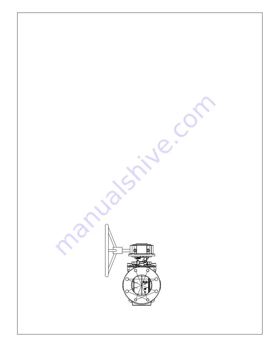
Fig. 2
INSTALLATION AND TESTING
NOTE:
Consult local codes and standards for valve placement and spacing
WARNING:
All water lines must be isolated or depressurized and drained before installing or maintaining valves.
Failure to do so may cause pressure to be released resulting in severe injury or death.
INSPECTION PRIOR TO INSTALLATION:
1. Visually inspect each valve for any foreign material in the interior of the valve, and remove it if present.
2. Inspect each valve in a similar manner as described in the "INSPECTION AFTER UNLOADING" section of this manual.
INSTALLATION:
1. Open and close the valve to verify proper operation. Close the valve if it is going into a trench.
2. Take care when handling the valve. Use the proper lifting areas on the valve. Do not lift the valve by the actuating devices.
Do not use chains or other lifting devices through the waterway.
3. During installation there is the possibility of foreign materials inadvertently entering the valve. Foreign material can
damage the internal working parts during operation of the gate valve. For this reason, gate valves should be installed in
the closed position. Each valve should be placed on firm footing in the trench to prevent settling and excessive strain on
the connection to the pipe. Piping systems should be supported and aligned to avoid damage to the valve.
4. Valves should be installed in the proper flow direction and with adequate clearance for actuating devices. The valves are
designed o allow flow in both directions, however, they are normally installed in a "standard" flow direction with the seat on
the downstream of the flow and the flow against the back of the plug.
5. Tighten the bolts and nuts in the crossover method shown in Fig. 2, to load the pipe and valve evenly and prevent stress
on the joints.
6. Valves buried in unusually deep trenches should have special provisions for operating the valve. Either a riser on the
stem to permit use of a normal key or a notation on the valve records that a long key will be required.
7. When valves with exposed gearing or operation mechanisms are buried below ground, a vault designed to allow pipe
clearance and prevent settling on the pipe should be provided. The operating nut should be accessible from the top
opening of the vault with a valve key. The size of the vault should provide for easy removal of the valve bonnet and
internal parts of the valve for purposes of repair. Consideration should be given to the possibility of groundwater and/or
surface water and to the need to provide the disposal of such water.
8. Valves installed above ground or in a plant piping system should be supported and aligned to avoid damage to the valves.
Valves should not be used to correct the misaligned piping.
9. Do not test valve systems to greater than the rated valve pressure.
10. With the valves in the open positions, flush the entire system to prevent the valves from closing on foreign materials and
damaging the seats or plugs.


