background image

F1

F55

page 9


MAINTENANCE PROCEDURES

The American AVK Series 2780 Dry Barrel Hydrant is designed 

to be a trouble free, easy to maintain hydrant. The following steps 

are recommended  to provide trouble free operation.

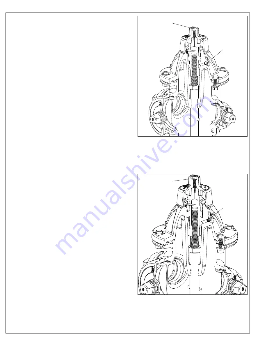
GREASE LUBRICATION 

 (Fig. 4A)

WARNING: 

On a partially disassembled hydrant under line 

pressure, pressing down on the stem could force open the Main 

Valve (F61) and allow it to slam shut, creating a water hammer. 

To prevent this during routine maintenance, first locate and be 

sure the supply valve is closed. Relieve the pressure on the 

Main Valve (F61) by momentarily opening and then closing the 

hydrant. Reopen the supply valve after the hydrant has been 

reassembled.

GREASE SERVICING FOR BONNETS WITH ZERK FITTINGS, 

(Fig. 4A

)

CAUTION

: For grease servicing, ensure that the Weathershield 

bolt has been loosened to prevent damage to the internal 

O-rings. 

1. Refilling is performed by loosening the Weathershield bolt 

    (F1) with a 5/16” or (8mm) hexagon key. 

2. Refill lubricant reservoir with a food grade grease using a 

    Grease gun on the Zerk Fitting (F75). 

3. Tighten the Weathershield Bolt.

OIL LUBRICATION 

 (Fig. 5A)

WARNING: 

On a partially disassembled hydrant under line 

pressure, pressing down on the stem could force open the Main 

Valve (F61) and allow it to slam shut, creating a water hammer. 

To prevent this during routine maintenance, first locate and be 

sure the supply valve is closed. Relieve the pressure on the 

Main Valve (F61) by momentarily opening and then closing the 

hydrant. Reopen the supply valve after the hydrant has been 

reassembled.

OIL SERVICING FOR BONNETS WITH BRASS PLUG, 

FIGURE 5A

1. Loosen the Weathershield bolt (F1) with a or 5/16”,(8mm) 

    hexagon key. This will allow the oil reservoir to breath and be 

    filled faster. 

2. Remove the Brass Plug (F55) with a 3/16” hexagon key. 

    Refill the oil reservoir with FDA approved food grade oil. 

3. Install the Brass Plug and tighten the Weathershield Bolt. 

    This should be done after any repairs or as required by local

    specifications.

Fig. 4A

Grease lubrication for bonnets 

with zerk fittings

F1

F75

Fig. 5A

Oil lubrication for bonnets 

with brass plug

Summary of Contents for 2700 SERIES

Page 1: ...NTS EXPLODED ASSEMBLY PARTS LIST INTRODUCTION DESCRIPTION RECEIVING AND STORAGE INSTALLATION AND TESTING INSTALLATION TESTING OPERATION AND MAINTENANCE HYDRANT TOOLS OPERATION MAINTENANCE PROCEDURES LUBRICATION INSPECTION DISASSEMBLY FOR INSPECTION REASSEMBLY AFTER INSPECTION REPAIR PROCEDURES TRAFFIC REPAIR KIT OPTIONAL EQUIPMENT EXTENSION KITS TAMPERGUARD WEATHERSHIELD THRUST BEARING OPERATING A...

Page 2: ...s Breakdown F1 F2 F5 F6 F7 F8 F9 F10 F8 F12 F13 F14 F15 F16 F17 F13 F18 F19 F23 F25 F26 F27 F30 F31 F32 F31 F34 F38 F3 F4 F11 F75 F55 F44 F31 F20 F21 F55 F22 F28 F29 F88 F34 F31 F33 F36 F37 F41 F17 F49 F46 F32 F53 F51 F53 F17 F54 F38 F61 F50 F67 F94 F60 F95 F55 F56 ...

Page 3: ...F36 Coupler Pin 420 Stainless steel F37 Breakable Stem Rod Coupling 431 Stainless steel F38 Spring Pin 304 Stainless steel F41 Lower Stem Rod Mild Steel 304 Stainless steel F42 Extension Coupling 304 Stainless steel F43 Extension Barrel Ductile Iron ASTM A536 F44 Upper Extension Barrel Bolt Zinc plate 304 316 Stainless steel F45 N A F46 Standpipe Flange Ductile Iron ASTM A536 F47 Monitor Elbow Duc...

Page 4: ... check to make sure all bolts are tight and all nozzles are properly installed See NOZZLE INSTALLATION Clean any dirt and debris from inside the hydrant base and from the hydrant lead 2 All hydrants shall be installed as plumb as possible 3 Consult local codes and standard for hydrant placement In general the following guidelines should be observed Locate hydrants to provide complete accessibility...

Page 5: ...ic model hydrants Drain Detail Caution When pouring thrust block do not cover drain holes 1 3 cubic yard drain field rock C o n c r e t e thrust block Supply Valve 6 2 min 2 Bury Concrete Grounding from hydrant base to Zinc Anode for providing cathodic protection Effective April 2015 Anode grounding wire not supplied ...

Page 6: ...E MAIN PRESSURE 1 Connect a pressure test pump to one of the hydrant s outlet nozzles 2 Open the highest outlet nozzle cap Open the hydrant valve a few turns Allow the hydrant to fill until water is at the bottom of the outlet nozzle 3 After all air has escaped tighten the outlet nozzle cap 4 Open the hydrant completely 5 Close the auxiliary valve 6 Pump up to test pressure usually 150 psi 1034 kP...

Page 7: ...page 6 Fig 2 Internal Drain Plugging F55 F51 ...

Page 8: ...ly one universal wrench is required regardless of bury depth 2 AVK Oilsaver Adapter Part Number 27 150 30 300 3 AVK Operating Wrench Part Number 27 150 30 700 4 AVK Seat Wrench Alignment Tool Part Number 27 150 30 500 METRIC AND INCH WRENCH REQUIREMENTS FOR AMERICAN AVK HYDRANTS PART INCH SIZE METRIC SIZE Weathershield Retaining Bolt Allen 5 16 8mm Thrust Nut Retaining Screw Allen 5 32 4mm Nozzle ...

Page 9: ...2 until the Main Valve F61 is fully open Approximately 19 to 21 turns The Stop Nut F11 should prevent the hydrant from opening beyond the fully open position Do not force the hydrant in the opening direction beyond full open as indicated by sudden resistance to turning If water does not flow when the hydrant is open it is probably due to a closed valve upstream from the hydrant 3 To close turn the...

Page 10: ...agon key 2 Refill lubricant reservoir with a food grade grease using a Grease gun on the Zerk Fitting F75 3 Tighten the Weathershield Bolt OIL LUBRICATION Fig 5A WARNING On a partially disassembled hydrant under line pressure pressing down on the stem could force open the Main Valve F61 and allow it to slam shut creating a water hammer To prevent this during routine maintenance first locate and be...

Page 11: ...r punch mark on the hose nozzle This mark should be in alignment with the Nozzle Retaining Screw F23 as shown in figure 6G 5 For Pumper Nozzles the dimple or punch mark is on the face of the cap end of the pumper nozzle as shown in figure 6J 6 If the dimple is not in alignment with the retaining screw F23 remove the retaining screw and rotate the nozzle until the alignment is correct 7 Apply a dro...

Page 12: ... the cap then finish removing the cap nozzle assembly See Fig 6E 5 Remove the old Hose Nozzle O ring F22 or Pumper Nozzle O ring F25 and replace with a new one 6 Lightly grease the o ring with a food grade grease that contains no acetate or silicone 7 Follow the steps in REASSEMBLY AFTER INSPECTION to reinstall the nozzles and caps NOZZLE REASSEMBLY AFTER INSPECTION 1 Insert the greased Cap Nozzle...

Page 13: ... 6A Fig 6B Fig 6C Fig 6D Fig 6E Fig 6F Fig 6G Fig 6H Fig 6J F28 F27 F26 F25 Dimple Dimple Dimple F23 F23 Nozzle lug rotated between nozzle section lugs to allow cap removal Fifth Lug Fifth Lug Secondary set screw Secondary set screw Secondary set screw ...

Page 14: ...ighten the Stop Nut F11 during re assembly See Fig 7D 6 Remove the six Bonnet Bolts F12 and associated hardware using 3 4 or 19mm wrenches Lift Bonnet F14 over the Upper Stem Rod F16 and set aside NOTE On oil filled hydrants to avoid draining of oil from the oil reservoir in the bonnet F14 press the Oilsaver sleeve See Fig 7E and 7F with the stop ring placed downward over the Upper Stem Rod F16 du...

Page 15: ... Nuts finger tight 4 Using the AVK Seat Wrench install the Stop Nut F11 Do not over tighten the Stop Nut 5 If required fill the lubrication reservoir with the appropriate food grade oil or grease that contains no acetate or silicone 6 Place one Anti Friction Washer F8 on the top and bottom of the Operating Nut F10 thrust collar See Fig 7A 7 Install the Operating Nut and Anti Friction Washers Tight...

Page 16: ...15 F1 F2 Fig 7A Fig 7B Fig 7C Fig 7D Fig 7E Fig 7F Fig 7G Fig 7H Fig 7J F3 F4 F8 F10 F11 F6 Oil Saver AVK Seat Wrench F16 AVK HydrantWrench F41 F38 F51 F88 F60 F53 F61 F17 F15 AVK Seat Wrench Alignment Tool ...

Page 17: ...move the hardware F30 31 34 from the Breakable Flange F33 Slide the Lock Ring F32 off of the Lower Barrel F49 See Fig 8 2 Remove the Spring Pins F38 from the Coupler Pins F36 in the Upper Stem Rod F16 and Lower Stem Rod F41 Remove and discard the broken Breakable Coupling F37 3 If required remove the Upper Stem Rod F16 from the hydrant head assembly by following the Warnings and steps 1 through 4 ...

Page 18: ...ver tighten the Stop Nut Fill the lubrication reservoir with the appropriate food grade oil or grease that contains no acetate or silicone 11 Place one Anti Friction Washer F8 on the top and bottom of the Operating Nut F10 thrust collar See Fig 7A 12 Install the Operating Nut and Anti Friction Washers 13 Lightly grease the o rings on the Thrust Nut F6 and screw the Thrust Nut into the Bonnet compl...

Page 19: ...ant Bury Tags F94 9 Remove the lower Spring Pin F38 and slide the lower Coupler Pin F36 from the Lower Stem Rod F41 Disconnect the Upper Stem Rod F16 along with the Stem Rod Coupling F37 from the Lower Stem Rod F41 Inspect the Stem Rod Coupling for damage and replace if necessary 10 Remove the Breakable Flange F33 and Lock Ring F32 Set aside for later re assembly 11 Install a Standpipe Flange F46 ...

Page 20: ... F11 Spin the stop nut down until it stops and then snug it about 1 4 turn tighter 30 Reinstall the Anti Friction Washer F8 in the oil reservoir of the Bonnet F14 31 If required refill the lubrication reservoir in the Bonnet F14 reservoir with a food grade oil or grease that contains no acetate or silicone 32 Reinstall the Operating Nut F10 Tighten the Operating Nut all the way until it is snug ag...

Page 21: ... F34 F49 Text THIS SIDE UP Detail B For hydrants manufactured prior to Sept 7 2010 Detail D Groove Standpipes installed with the recessed side towards the Lock Rings Detail C For hydrants manufactured after Sept 7 2010 Detail E As of Nov 1 2011 the Spider and Spider Bolt are no longer required in AVK dry barrel hydrants F41 ...

Page 22: ...th a 5 32 or 4mm hex key 3 Install the new Tamper Resistant Lockplate F94 using the high strength Lockplat Screw supplied in the kit F95 with a 5mm hex key NOTE The high strength screw must be used to increase the strength of the entire assembly 4 Install new Tamper Resistant Weathershield F93 using the Weathershield Bolt F1 5 Align the holes in Tamper Resistant Weathershield F93 and Tamper Resist...

Page 23: ...nti Friction Washers have been discarded verify that the Stop Nut F11 is secure at the bottom of the threads of the Upper Stem Rod F16 Use the AVK T Wrench to ensure that the Stop Nut is not backed off 5 Replace them with the new Operating Nut F10 and one Anti Friction Washer F8 placed below the Operating Nut shoulder 6 Install the Lubrication Hole Seal F9 into the threaded hole in the top of the ...

Page 24: ...tive action Disassemble the Operating Nut Thrust Nut assembly Clean and re lubricate using a food grade grease PROBLEM Nozzle facing the wrong direction Corrective action Loosen the Nozzle Section hardware and carefully rotate the Nozzle Section to the desired position Tighten the mounting hardware to 80 Ft Lbs PROBLEM Hydrant opens but will not close Probable Cause The Breakable Coupling or Exten...

Page 25: ...e and verify that the supply valve is fully open PROBLEM Hydrant is leaking from a nozzle Probable Cause Nozzle O ring or Cap Gasket is damaged Corrective action Replace damaged O ring or Gasket PROBLEM Hydrant is leaking from the operating Nut Probable Cause Stem Seal O rings have failed Corrective action Replace the Stem Seal O rings and Thrust Nut O rings if necessary Refill hydrant with a food...

Page 26: ...AVK this warranty shall be void As to motors gearing or accessory equipment purchased by American AVK Company from others manufacturers and used or incorporated into American AVK Company s products those manufacturers warranties shall apply American AVK Company will honor all reasonable costs to repair or replace any American AVK Company Dry Barrel Fire Hydrant found to be defective American AVK C...

Page 27: ...page 26 ...

Reviews: