Jump to: Table of Content
2022/03/08
Page : 12
5.3.3
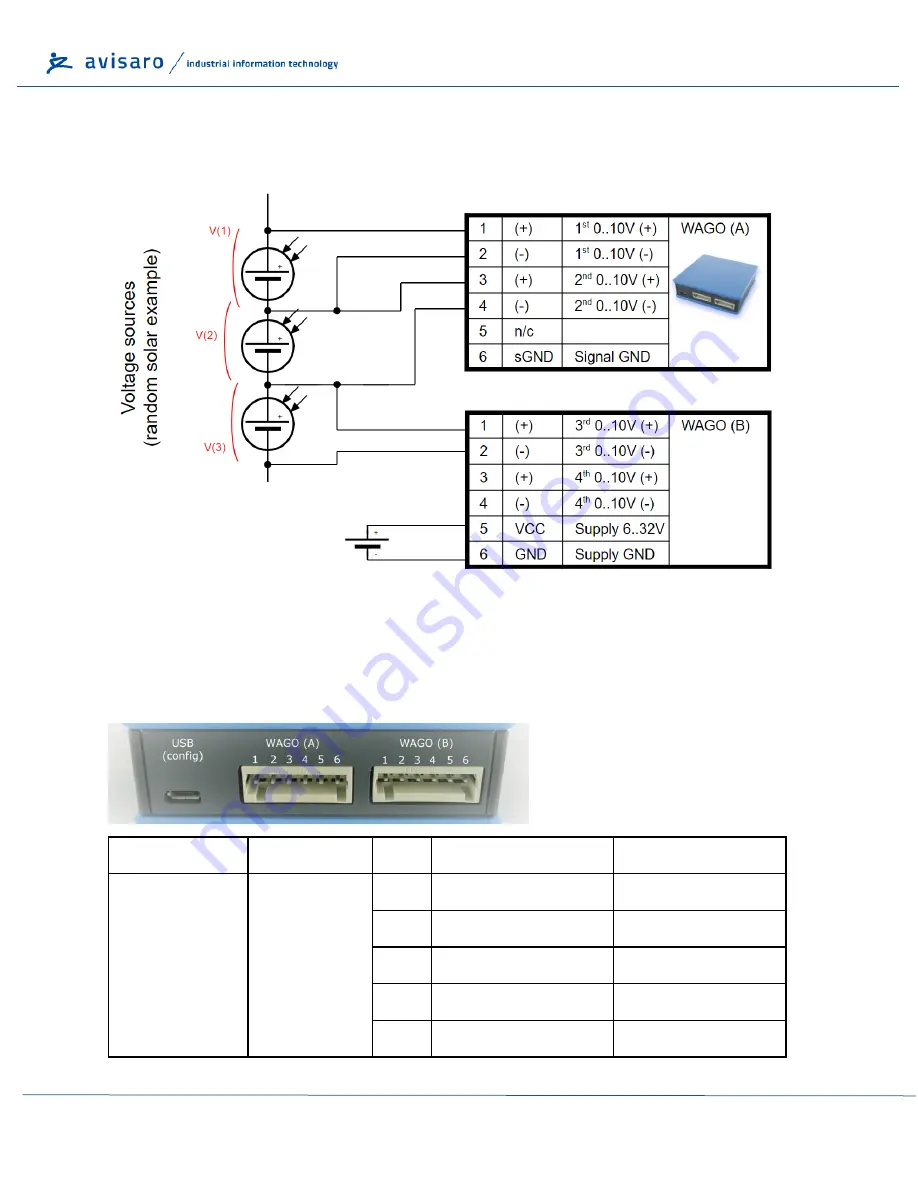
Example: Wiring “differential” measurement
The data logger allows for true differential measurement. The following diagram illustrates the wiring.
5.3.4
WAGO - 4x 0..10V
Interface (“M4
99
24” / “C4
99
24”)
Connector
Interface
Pin
Signal
Direction
WAGO A
1
st
& 2
nd
0..10V
1
1
st
0..10V (+)
2
1
st
0..10V (-)
3
2
nd
0..10V (+)
4
2
nd
0..10V (-)
5
not connected


