background image

Card RIser 1 Slot 1 (labeled 10 in the diagram). Do not remove this card as part of this upgrade.

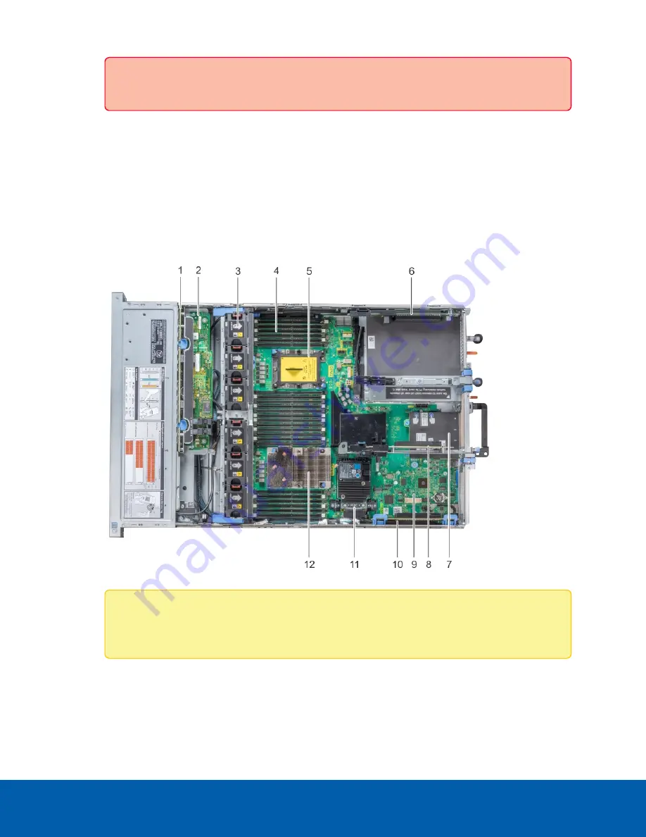
The components affected by the AI NVR Standard Performance Upgrade Kit are:


l

4— Memory module
The 2 DIMMs in the upgrade kit are installed here.


l

5—CPU2 processor and heat sink module socket (with dust cover) 
The second CPU in the performance kit is installed here.


l

10—Expansion Card Riser 1
The second P2200 GPU card is installed on the middle slot (Slot 2) of this riser, above the 
original GPU card in the lowest slot (slot 1).

Note: 

The other components pointed out in the diagram are not affected by installing the 

AI NVR Standard Performance Kit..

2. Installing the CPU

You need the processor bracket, processor (CPU), and heatsink provided in the kit to complete this 

2. Installing the CPU

7

Summary of Contents for AI NVR Standard Performance Kit

Page 1: ...AI NVRStandardPerformance Kit Installation Guide AINVR STD PRK For AINVR STD 1 ...

Page 2: ...to any copyright industrial design trademark patent or other intellectual property rights of Avigilon Corporation or its licensors This document has been compiled and published using product descriptions and specifications available at the time of publication The contents of this document and the specifications of the products discussed herein are subject to change without notice Avigilon Corporat...

Page 3: ...Tools 4 Installing the AI NVR Standard Performance Kit 5 1 Removing the AI NVR Cover 6 2 Installing the CPU 7 3 Installing Additional RAM 10 4 Installing the New GPU card 12 5 Restoring the Removed Components 13 6 Confirming the Installation 13 For More Information 15 3 ...

Page 4: ...software Part Number Description AINVR STD PRK AI NVR Standard Performance Upgrade Kit Note If the AI NVR is an operating part of your security system be aware that it must be shut down to complete this procedure Confirm Package Contents Confirm that the kit you are installing contains the following components o 1 Intel Xeon CPU o 1 processor bracket o 1 heat sink o 2 8GB RDIMM o 1 P2200 GPU Requi...

Page 5: ... system cover while the system is powered on may expose you to a risk of electric shock 3 Disconnect the AI NVR from the electrical outlet and disconnect the peripherals Important It is recommended that you always use an antistatic mat and antistatic strap while working on components inside the system 4 If applicable remove the system from the rack Important Whenever you need to lift the system ge...

Page 6: ...cover if you are removing the cover of an AI NVR for the first time 4 Remove the air shroud by holding it at both ends and lifting it away from the system 5 Remove the black plastic protective cover over the socket Press the 2 blue clips and lift off the cover The protective cover is no longer needed and can be recycled 6 View the interior of the AI NVR and identify the locations where the compone...

Page 7: ...h dust cover The second CPU in the performance kit is installed here l 10 Expansion Card Riser 1 The second P2200 GPU card is installed on the middle slot Slot 2 of this riser above the original GPU card in the lowest slot slot 1 Note The other components pointed out in the diagram are not affected by installing the AI NVR Standard Performance Kit 2 Installing the CPU You need the processor bracke...

Page 8: ...aligned with the pin 1 indicator on the processor before placing the bracket 5 Unpack the heatsink Be careful not to touch the thermal paste that is pre applied to the bottom of the heatsink 6 Place the heat sink on the processor and push down on the base of the heat sink until the bracket locks onto the heat sink Important To avoid damaging the fins on the heat sink do not press down on the heat ...

Page 9: ...rocessor and heat sink module on the processor socket Important Ensure that the processor and heat sink module is held parallel to the system board to prevent damaging the components 8 Push the blue retention clips inward to allow the heat sink to drop into place 2 Installing the CPU 9 ...

Page 10: ...ention clips when the screws are partially tightened follow these steps to secure the module a Completely loosen both of the heat sink screws b Lower the processor and heat sink module on to the blue retention clips following the procedure as described in step 8 above c Secure the processor and heat sink module to the system board following the instructions as described in step 9 above 3 Installin...

Page 11: ... the white ejector clips shown as black in the diagram on each side of the empty memory module sockets outward to allow the memory modules to be inserted into the sockets 3 Align the edge connector of the memory modules with the alignment key of the sockets and press the memory modules into sockets until the socket levers click into place Important Do not apply pressure at the center of the memory...

Page 12: ...4 Remove the filler bracket Tip Store the filler bracket for future use Filler brackets must be installed in empty expansion card slots to maintain Federal Communications Commission FCC certification of the system The brackets also keep dust and dirt out of the system and aid in proper cooling and airflow inside the system 5 Pull the expansion card latch 6 Align the connector on the GPU card with ...

Page 13: ...ed and removed to install the kit remount it into the rack 4 Reconnect all the cables to the recorder 5 Power the recorder 6 Confirming the Installation Verify the upgrade is successful 1 Log in to the ACC Client on a workstation on the same network as the AI NVR 2 In the System Explorer click Site Setup and click Site to expand the site containing the upgraded AI NVR 3 Click to select the upgrade...

Page 14: ... Under the General Information heading the sum of Memory usage and System Available Memory should be approximately 32 GB 32 000 MB d Under the Temperature Probes heading you should see readings for CPU1 and CPU2 6 Verify that the analytics load capacity has increased a In the System Explorer select the upgraded AI NVR b In the New Task menu click Server Analytics For more information see the Enabl...

Page 15: ...Information For additional product documentation and software and firmware upgrades visit avigilon com support Technical Support Contact Avigilon Technical Support at avigilon com contact For More Information 15 ...

Reviews: