2
Installing the Hardware and Setting Up Your System
64
Connecting Control and Communications Cables
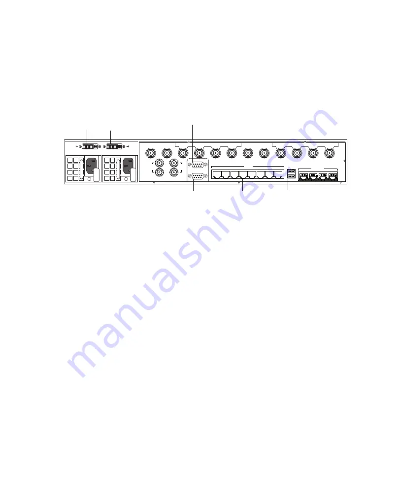
The following figure identifies the connectors used to connect the control and
communication cables. The illustration shows the rear of the MPEG-2 HD model. The
location of the control and communication connections is the same for all models. For the
exact location of the control and communication connectors, see
For more information, see the following topics:
•
“Connecting USB Devices (Mouse and Keyboard)” on page 65
•
“Connecting Ethernet Cables” on page 66
•
“Connecting to AirSpeed Multi Stream Over the Network” on page 67
•
“Connecting Expansion Port Cables” on page 68
•
“Connecting Remote Serial Cables” on page 69
•
“Connecting the Console Cables” on page 69
Expansion
Port 1
Expansion
Port 2
Console
VGA
USB
Ethernet
Serial
OUT
1
4
2
3
5
6
7
8
IN
1
2
IN
5
6
EXPANSION
PORT 1
EXPANSION
PORT 2
USB
CONSOLE
VGA
SERIAL
ETHERNET
1
2
3
4
1
2
3
4
5
6
7
8
OUT
REF
IN/THRU
LTC
IN/THRU
Summary of Contents for AirSpeed series
Page 1: ...Avid AirSpeed Multi Stream Installation and User s Guide...
Page 16: ...16...
Page 20: ...20...
Page 80: ...2 Installing the Hardware and Setting Up Your System 80...
Page 121: ...Optional AirSpeed Multi Stream Configuration Procedures 121 5 Click the Languages tab...
Page 190: ...5 Working with Clips 190...
Page 224: ...7 Working with the Remote Console 224...
Page 264: ...B Performing Hardware Diagnostics 264...
Page 269: ...Setting Up Network Teaming 269...
Page 270: ...C Network Teaming 270...


