background image


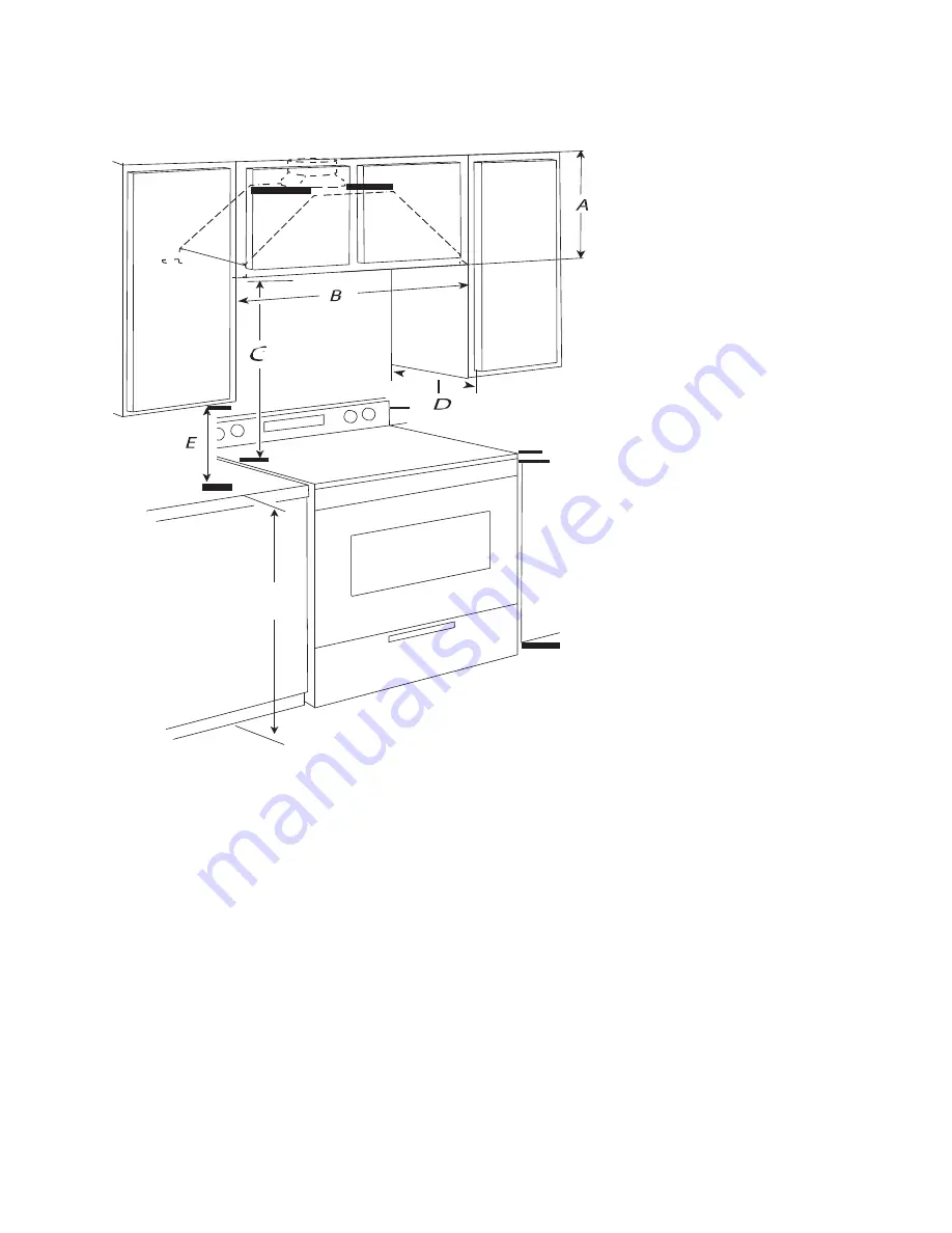
Dimensions du placard 


        F 


A. 

Hauteur minimum du placard: 12” (30,5 cm)


B. 

Largeur de l’ouverture du placard : 30” (76,2 cm)  

C. 

Distance minimum suggérée: 26’’ (66,04 cm) minimum à partir du haut d’une surface de cuisson électrique 
et 30‘’ (76,2 cm) minimum à partir d’une surface de cuisson au gaz;  
Distance maximum suggérée: 30‘’ (76,2 cm) maximum à partir du haut d’une surface de cuisson électrique 
et 36‘’ (91,44 cm) maximum à partir d’une surface de cuisson au gaz. 

D. 

Profondeur du placard: 12” (30,5 cm) 

E. 

Dégagement minimum entre le bas du placard et le plan de travail est de 15” (38,1 cm) 

F. 

Hauteur du placard du bas est de 36” (91,44 cm


Pour l’installation à partir de la surface de cuisson électrique:  

 
Montez cette hotte de sorte à ce que le bord ne soit pas inférieur au minimum de 

26

’’ (66,04 cm) au-dessus de la surface 

de cuisson.   
 
Pour l’installation à partir de la surface de cuisson au gaz:  

 
Montez cette hotte de sorte à ce que le bord ne soit pas inférieur au minimum de 

30

’’ (76,2 cm) au-dessus de la surface 

de cuisson.   


Summary of Contents for AVC-276PS-COLORADO

Page 1: ...e encastrable 28 27 6 28 27 6 Built in Hood IMPORTANT Lire et conserver ces instructions Read and save these instructions NOTE Installateur Laissez ce manuel au propriétaire Propriétaire Conservez ce guide pour référence ultérieure Installer Leave this manual with the homeowner Homeowner Keep this guide for future reference ...

Page 2: ...PLET AVANT DE COMMENCER L INSTALLATION DE L APPAREIL DOIT RESPECTER TOUS LES CODES EN VIGUEUR IMPORTANT Conservez ces instructions afin de pouvoir les remettre à l inspecteur électricien de votre région INSTALLATEUR Veuillez laisser ces instructions avec l appareil pour le propriétaire PROPRIÉTAIRE Veuillez conserver ces instructions pour pouvoir vous y référer plus tard AVERTISSEMENT DE SÉCURITÉ ...

Page 3: ...quatement les gaz veillez à acheminer l air aspiré par un conduit jusqu à l extérieur ne pas décharger l air aspiré dans un espace vide du bâtiment comme une cavité murale un plafond un grenier un vide sanitaire ou un garage AVERTISSEMENT POUR RÉDUIRE LE RISQUE D INCENDIE UTILISEZ UNIQUEMENT DES CONDUITS MÉTALLIQUES AVERTISSEMENT POUR MINIMISER LE RISQUE D UN FEU DE GRAISSE SUR LA CUISINIÈRE ɷ Ne ...

Page 4: ...areil La plaque signalétique de l appareil est située derrière le filtre sur la paroi arrière gauche de la hotte Installez la hotte de cuisinière à distance de toute zone exposée à des courants d air comme les fenêtres portes et bouches de chauffage Respectez les dimensions indiquées pour les ouvertures à découper dans les placards Ces dimensions tiennent compte des valeurs minimales des dégagemen...

Page 5: ...Hotte encastrable 27 6 70 1 cm Dimension DIM A 27 1 2 68 6 cm DIM B 26 66 cm DIM C 5 8 1 6 cm DIM D 10 1 4 26 cm DIM E 9 7 8 25 1 cm DIM F 5 8 1 6 cm DIM G 12 3 8 31 43 cm DIM H 6 14 8 cm Dimensions ...

Page 6: ...imum à partir d une surface de cuisson au gaz D Profondeur du placard 12 30 5 cm E Dégagement minimum entre le bas du placard et le plan de travail est de 15 38 1 cm F Hauteur du placard du bas est de 36 91 44 cm Pour l installation à partir de la surface de cuisson électrique Montez cette hotte de sorte à ce que le bord ne soit pas inférieur au minimum de 26 66 04 cm au dessus de la surface de cu...

Page 7: ...brides de serrage À l aide d un produit de calfeutrage assurez l étanchéité autour de la bouche de décharge vers l extérieur qui passe à travers le mur ou le toit La taille du conduit doit être uniforme Air d appoint Les codes du bâtiment locaux peuvent exiger l emploi d un système de renouvellement d air introduction d air d appoint lors de l utilisation d un système d aspiration de débit supérie...

Page 8: ... Pour calculer la longueur effective du circuit d évacuation nécessaire additionnez les longueurs équivalentes en pieds mètres de toutes les composantes utilisées dans le circuit Exemple de circuit d évacuation 6 15 2 cm Composante 6 15 2 cm Bouche de Coude à 45 2 5 pi Coude à 90 décharge 0 8 m murale Coude à 90 5 0 pi 1 5 m Longueur maximum 35 pi 10 7 m 1 Coude à 90 5 pi 1 5 m 1 Bouche de décharg...

Page 9: ...ents locaux Si une prise n est pas disponible le client a la responsabilité et l obligation de faire installer par un électricien qualifié une prise de courant correctement reliée à la terre La prise à 3 broches reliée à la terre doit se trouver dans un placard situé au dessus de la hotte à une distance maximale de 29 1 2 75 cm à partir du point duquel le cordon d alimentation sort de la hotte La ...

Page 10: ...ouverte AVERTISSEMENT Risque de poids excessif Utilisez deux ou plus de personnes pour déplacer et installer la hotte de la cuisinière Le non respect de cette instruction peut causer une blessure au dos ou d autre blessure Ouverture découpée du placard pour la hotte 1 Utilisez une scie sauteuse ou scie à guichet pour découper une ouverture dans le fond du placard à l intérieur du cadre du placard ...

Page 11: ...eur à travers le mur 1 Fixez le raccord de transition du conduit de 6 15 2 cm au sommet de la caisse de la hotte à l aide de deux vis de 3 5 x 9 5 mm Assemblez le conduit d évacuation qui sera utilisé sur le raccord de transition du conduit de 6 15 2 cm 2 Mesurez la distance entre le bas de la caisse de la hotte et l axe central horizontal de l ouverture d évacuation A A B C A Mesure A B Axe centr...

Page 12: ...ble de rallonge Le non respect de ces instructions peut causer un décès un incendie ou un choc électrique 2 Branchez le cordon d alimentation à 3 broches dans la prise à 3 alvéoles reliée à la terre située dans le placard qui se trouve au dessus de la hotte 3 Contrôlez le fonctionnement du ventilateur de la hotte et de la lampe Voir la section Instructions d utilisation Si la hotte ne fonctionne p...

Page 13: ... hotte D A B C A Commandes du ventilateur et de l éclairage B Filtre à graisse C Poignée du filtre à graisse D Logement des lampes LED Commandes de la hotte de cuisinière Utilisation de la lampe Le bouton Lumière contrôle toutes les lampes Appuyez une fois pour On marche et une deuxième fois pour Off arrêt Utilisation du ventilateur Les boutons VITESSE vitesse du ventilateur activent le ventilateu...

Page 14: ... 2 Lavez les filtres métalliques selon le besoin au lave vaisselle ou avec une solution de détergent chaude 3 Réinstallez le filtre en s assurant que les poignées à ressort sont orientées vers l avant Insérez le filtre à graisse métallique dans la rainure supérieure 4 Tirez vers le bas la poignée à ressort 5 Poussez le filtre métallique vers le haut et relâchez la poignée pour l emboîter 6 Répétez...

Page 15: ...450 963 1303 ou 1 888 651 2534 service agintl qc ca Toutes les réclamations doivent inclure le numéro de modèle de l unité le numéro de série de l unité une preuve d achat la date d installation et tous les renseignements pertinents venant appuyer le présumé défaut AUCUN DOMMAGE INDIRECT AVG n est aucunement responsable des pertes économiques de profit ou des dommages directs ou indirects y compri...

Page 16: ...RUCTIONS PLEASE READ THE ENTIRE INSTRUCTIONS BEFORE YOU BEGIN INSTALLATION OF THE UNIT MUST RESPECT ALL CODES IMPORTANT Keep these instructions in order to provide them to the electrical inspector in your area INSTALLER Please leave these instructions with the owner of the unit PROPRIÉTAIRE Keep these instructions for future reference Security warning Turn off the power circuit in the electrical p...

Page 17: ...ION To minimize the risk of fire and to properly exhaust air be sure to route the air sucked through a pipe to the outside not to discharge the air sucked into an empty space of the building as a cavity wall ceiling attic crawl space or garage WARNING TO REDUCE THE RISK OF FIRE USE ONLY METAL DUCTWORK WARNING TO REDUCE THE RISK OF A GREASE FIRE PLEASE OBSERVE THE FOLLOWING INSTRUCTIONS ɷ Never lea...

Page 18: ...pecified on the nameplate of the unit The unit s rating plate is located behind the filter on the left rear wall of the hood Install the range hood away from any area that is exposed to drafts such as windows doors and heating vents Follow the dimensions indicated for openings to be cut in cabinets These dimensions provide minimum clearance separation Before making cut outs refer to the instructio...

Page 19: ...nsions of the product Built In Hood 27 6 70 1 cm Dimension DIM A 27 1 2 68 6 cm DIM B 26 66 cm DIM C 5 8 1 6 cm DIM D 10 1 4 26 cm DIM E 9 7 8 25 1 cm DIM F 5 8 1 6 cm DIM G 12 3 8 31 43 cm DIM H 6 14 8 cm ...

Page 20: ...c cooktop and 36 91 44cm maximum from the top of a gas cooktop E Depth of the cabinet 12 30 5 cm F Minimum clearance between the work plan and the bottom of the cabinet 15 38 1 cm G Height of lower cabinet of 36 91 44 cm For installation from the cooking surface of an electric cooktop Assemble the hood so that the lower edge is no less than 26 66 04 cm above the cooking surface For installation fr...

Page 21: ...s Using caulking seal around the exhaust hood to the outside that passes through the wall or roof The size of the pipe must be the same throughout Air booster Local building codes may require the use of an air exchange system extra air supply when using a flow suction system that exceeds a specified value cubic feet per minute The rate specified in cubic feet per minute varies from one jurisdictio...

Page 22: ...hree 90 elbows To calculate the length of the exhaust system required add the equivalent length feet meters of all the components used in the circuit Example of an exhaust system 6 15 2 cm pipe Component 6 15 2 cm Mural 45 Elbow 2 5 ft 90 Elbow discharge 0 8 m exit 90 Elbow 5 0 ft 1 5 m Maximum length 35 ft 10 7 m 1 90 Elbow 5 ft 1 5 m 1 Discharge exit 5 ft 1 5 m 1 Pipe straight 9 ft 2 75 m Total ...

Page 23: ...codes and regulations If an outlet is not available the customer has the responsibility and obligation to have it installed by a qualified electrician The 3 prong grounded outlet must be installed in the cabinet situated above the hood at a maximum distance of 29 1 2 75 cm from the point that the plug leaves the hood The 3 prong grounded outlet must be accessible once the hood is installed See ill...

Page 24: ...surface WARNING Risk of excessive weight Use two or more people to move and install range hood Failure to do so can result in back injury or other injuries Cut out opening of the cabinet for the hood 1 Use a jigsaw or reciprocator saw to cut a hole in the bottom of the cabinet on the inside of the frame of the cabinet NOTE For cabinets without frames a rim at the front and the rear of 1 9 cm is re...

Page 25: ...ve Discharge toward the exterior through the wall 1 Attach the transition fitting 6 15 2 cm duct at the top of the body of the hood using two 3 5 x 9 5 mm screws Assemble the exhaust duct to be used on the 6 15 2 cm transition fitting duct 2 Measure the distance between the bottom of the body of the hood and the horizontal centerline of the discharge opening A A B C A Mesure A B Central axis C Cir...

Page 26: ...o the ground Do not use an adapter Do not use an extension cord Failure to follow these instructions can result in death fire or electric shock 1 Plug the 3 pin power cord into the 3 prong grounded outlet located in the cabinet that is above the hood 2 Check the fan hood and lamp See Using the hood section If the hood does not work determine if a circuit breaker has tripped or a household fuse has...

Page 27: ...f the hood D A B C A Controls of the fan and lights B Grease filters C Handle for the grease filters D Lamp housings LED Controls for the cooktop hood Lamp operation The button Light controls all lamps Press once to turn On and a second time to turn Off Using the fan The BLOWER SPEED fan speed buttons activate the fan and control the speed of the fan and the noise level for quiet operation The spe...

Page 28: ...ilter downward A A Spring handle 2 Wash metal filters as needed in dishwasher or hot detergent solution 3 Reinstall the filter ensuring that the spring handles are facing forward Insert the metal grease filter in the upper groove 4 Pull down the handle spring 5 Push the metal filter upwards and release the handle to encase it 6 Repeat steps 1 to 5 for the other filter Replacing an LED lamp Interru...

Page 29: ...evard West Laval Québec H7L 6B1 Tel 450 963 1303 or 1 888 651 2534 service agintl qc ca All claims must include the unit s model number serial number of the unit a proof of purchase installation date and relevant information to support the alleged defect NO INDIRECT DAMMAGE AVG is not responsible for economic losses profit or any direct or indirect damages including without limitation losses or da...

Reviews: