background image


E-2


A

A

V

V

e

e

r

r

M

M

e

e

d

d

i

i

a

a

®

®


A

A

V

V

e

e

r

r

V

V

i

i

s

s

i

i

o

o

n

n


S

S

P

P

B

B

3

3

7

7

0

0


P

P

a

a

r

r

t

t

s

s


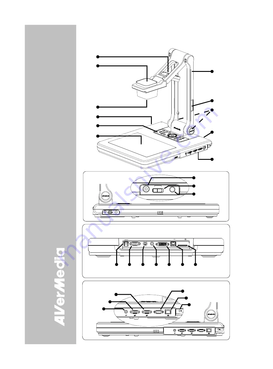
The illustrations below identify the parts of SPB370. 

1. Overhead 

light 

2. Camera 

head 

3. Camera 

lens 

4. Left 

panel 

5. Control 

panel 

6. Light 

box 

7. Arm 
8. Label 

slot 

9. IR 

sensors 

10. Rear panel 
11. Right panel 
12.  MIC IN port 
13.  Video output switch 
14.  Light box power 

button 

15.  DC 12V port 
16.  RGB output port 
17.  S-Video output port 
18.  Video output port 

(RCA/Composite) 

19.  DVI-I output port 
20. USB port 
21.  SD card slot 
22.  RGB IN 1 port 
23.  RGB IN 2 port 
24.  Audio out port 
25. RS-232 port 
26.  Ethernet (RJ-45) port  
27. Antitheft slot 


(1)

(4)

(6)

(5)

(2)

(3)

(11)

(7)

(9)

(8)

(10)

ETHER

NE T

RS-23

2

RGB I

N 1

RGB IN

 2

AUDIO

 OU

T

IO IO

I


Left Pane l

(12)
(13)
(14)

LIGHT BOX

MIC IN

VIDEO OUTPU

T

SPB370

TV

RGB

LIGHT BOX

MIC IN

VIDEO OUTPUT

TV

RGB


Rea r Pane l

(15) (16)

(20) (21)

(19)

(18)

(17)

RGB

OUTPUT

DC 12V

VIDEO

OUTPUT

S-VIDEO

OUTPUT

DVI-I OUTPUT

USB

SD CARD


ETHERNE

T

RS-232

RGB IN 1

RGB IN 2

AUDIO OU

T

IOIOI

ETHERNET

RS-232

RGB IN 1

RGB IN 2

AUDIO OU T

IOIOI

Righ t Pane l

(25)

(26)

(27)

(22)

(23)

(24)


Summary of Contents for AVerVision SPB370

Page 1: ...of the laws of the Member States relating to Electromagnetic Compatibility Directive 2004 108 EEC Warning This is a Class A product In a domestic environment this product may cause radio interference...

Page 2: ...nd corrosion can damage this remote control dispose of batteries safely Do not mix old and new batteries Do not mix different types of batteries alkaline standard carbon zinc or rechargeable nickel ca...

Page 3: ...nnection E 7 Inserting and Ejecting a SD Card E 8 Setting Up SPB370 E 8 Arm E 8 Camera Head E 8 Overhead Light E 9 Infrared Sensor E 9 Light Box E 9 Anti glare E 9 Microscope Connection E 10 Control P...

Page 4: ......

Page 5: ...s interactive visualizer displays documents negatives transparencies and 3D objects onto a TV LCD or DLP projector making demonstrations a snap The advanced features of the AVerVision SPB370 make it a...

Page 6: ...ort 18 Video output port RCA Composite 19 DVI I output port 20 USB port 21 SD card slot 22 RGB IN 1 port 23 RGB IN 2 port 24 Audio out port 25 RS 232 port 26 Ethernet RJ 45 port 27 Antitheft slot 1 4...

Page 7: ...ment 4 Video output RCA Composite Output the signal from the camera or the captured images from the memory source on TV or Video equipment 5 DVI I output Output the signal from the camera RGB IN port...

Page 8: ...t Use an RJ 45 Ethernet cable and connect it to RJ 45 Ethernet port This connection allows using any Web browser to access the embedded web server and remotely control SPB370 Make sure SPB370 is conne...

Page 9: ...ble not supplied Connecting a TV Locate the VIDEO yellow S VIDEO or SCART RGB input port of the TV or Video equipment i e VCR to record your presentation on a videotape and connect it to S VIDEO or VI...

Page 10: ...entation on screen and connect it to RGB IN 1 or RGB IN 2 ports of SPB370 The video signal from the RGB INPUT port is streamed to RGB and DVI I OUTPUT ports only and displayed on the screen even in st...

Page 11: ...ble AUDIO I N P U T Te l e v i s i o n V C R S t e r e o Desktop Laptop RCA Jack to 3 5mm Mono Plug Adapter not supplied RCA cable Connecting a Computer via USB Connection Locate the USB port of the c...

Page 12: ...p S SP PB B3 37 70 0 This section provides useful tips on how to adjust the SPB370 to meet your needs Arm The arm must be unfolded fully in upright position LIGHTBOX SPB350 VIDEO OUTPUT TV RGB 90 90 C...

Page 13: ...of SPB370 to turn on and off light Use this to view negatives film and 35mm slides DO NOT place an object weighing more than 8kg on top of the light box LightBoxButton negativefilm photos document lig...

Page 14: ...ope Adapter optional Microscope Control Panel Light Color The LED power button on the control panel of SPB370 indicates the status of the unit Color Description Blue The unit is in operating mode Oran...

Page 15: ...2 AAA size batteries are provided into the battery compartment at the back of the remote Use the figure and descriptions below as a reference for remote control functions Name Function 1 POWER Turn th...

Page 16: ...mory source permanently in Playback mode 8 ROTATE Turn the image by 90 in Camera mode and 180 in full screen Playback mode 9 TIMER Display the OSD timer menu and use or buttons to select SET TIME to s...

Page 17: ...MP 2 1 13 12 11 3 6 5 7 4 10 9 8 14 Name Function 1 POWER Turn the unit on off 2 SOURCE Switch between Camera Playback and PC mode To skip Playback and immediately switch to PC mode press the SOURCE b...

Page 18: ...u and sub menu See Menu Functions for more details 12 LAMP Turn the overhead light on off 13 Source LED Indicator Indicate the selected Source mode either in Camera Playback or PC 14 Video Output LED...

Page 19: ...E 15 English Deutsch Fran ais Italiano Espa ol esky O OS SD D N Na av vi ig ga at ti io on n T Tr re ee e VIDEO OUTPUT OSD For TV output RESOLUTION is not included in the menu list PLAYBACK OSD...

Page 20: ...select and turn on either AVERBOX or AVERVISOR Then press ENTER to make a selection Only one feature can be used at a time AVerBox overlays a frame on the presentation screen Selecting SHADE changes t...

Page 21: ...ave the setting and exit IMAGE EXPOSURE WHITE BALANCE BRIGHTNESS CONTRAST RESOLUTION AUTO MANUAL FLICKER NIGHT VIEW SETTING IMAGE EXPOSURE Press and use or buttons to select between Auto Manual Flicke...

Page 22: ...till image Mass Storage transfer the captured images from the memory source to computer hard disk SAVE PROFILE 1 PROFILE 2 PROFILE 3 SETTING SAVE Use or buttons to select which user setting profile nu...

Page 23: ...o Output NTSC or PAL Image Capture Up to 80 Frames Built In Memory 32MB NAND Flash Memory Optics Lens F3 5 f 6 60 mm Auto Focus Shooting Area 310mm x 233mm AVer Optical Zoom 25 6x 8x optical 3 2x AVER...

Page 24: ...i is ss si io on n S Sp pe ec c Start bit 1 bit Data bit 8 bit Stop bit 1 bit Parity bit None X parameter None Baud rate Communication speed 9600bds R RS S 2 23 32 2C C C Co om mm mu un ni ic ca at ti...

Page 25: ...0x02 0x01 Value 0 255 1 Brightness Value 0x03 Value 0 63 0x00 1 Contrast Value 0x04 Value 0 255 0x00 1 Rotate 0 degree 0x06 0x00 0x00 0x5D Rotate 90 degree 0x06 0x01 0x00 0x5C Rotate 180 degree 0x06 0...

Page 26: ...witch the source to VGA 5 Make sure the TV RGB switch is properly set based on your display output There is no computer signal on the presentation screen When you turn on the computer it will auto det...

Page 27: ...ced product Limitations of Warranty AVerMedia makes no warranties to any third party You are responsible for all claims damages settlements expenses and attorneys fees with respect to claims made agai...

Reviews: