background image


AL37219C-EVB-A2-User Manual-1.1-20090327


©2008-2009 Copyright by AverLogic Technologies, Corp.                                                                10  

4 System Menu  

4.1 OSD Main Menu  

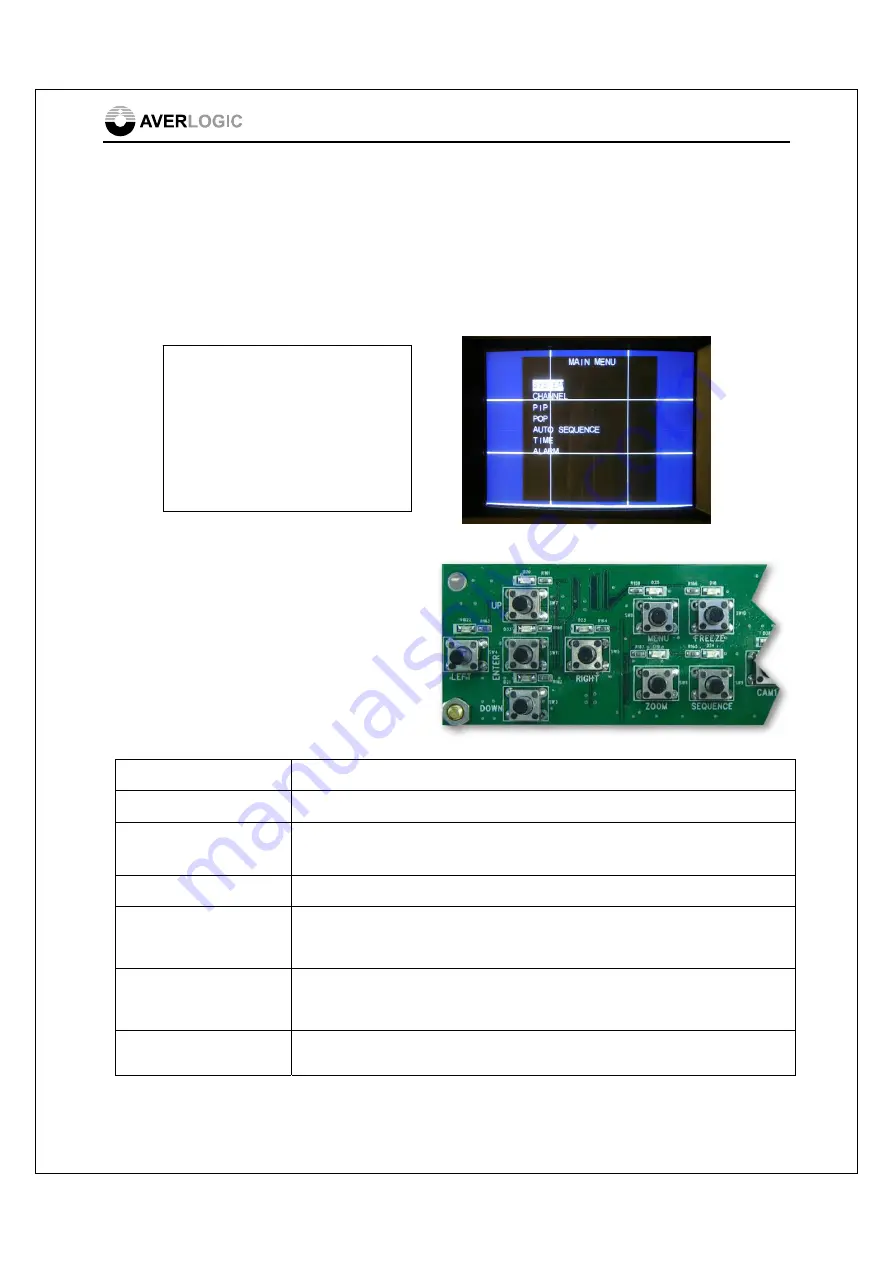
You can bring up the OSD (On Screen Display) Main Menu by pressing the MENU 

key on the Keypad panel.   The OSD screens are used to configure various aspects of 

the mainboard and display screens.


4.2 Navigating the OSD Menu 
using the Keypad 

Once you have entered the OSD Menu, 
you can use the Keypad Panel to 
navigate the menu and submenus.  
Navigation keys are explained below: 


Key Function 

ENTER Key 

This key is used to drill down into a submenu or exit from a submenu. 

MENU Key 

This key is used to initially bring up the OSD main menu. This key is also 

used to exit from the OSD menu. 

UP/DOWN Keys 

These keys are used to move up and down the menus. 

FREEZE Key 

This key is used as a 

Tab 

key to move forward (horizontally) through the 

different option fields of a configuration line item.  This only applies to 
configuration line items that have more than one field.  


Sequence Key 

This key is used as a 

Tab 

key to move backward (horizontally) through the 

different option fields of a configuration line item.  This only applies to 
configuration line items that have more than one field.   

LEFT/RIGHT Keys 

These keys are used to flip through the different selections for an option 
field (RIGHT-forward, LEFT-backward). 

MAIN MENU 

SYSTEM 

CHANNEL 

PIP 

POP 

AUTO SEQUENCE 

TIME 

ALARM


Summary of Contents for AL37219C-EVB-A2

Page 1: ...RMATION FURNISHED BY AVERLOGIC IS BELIEVED TO BE ACCURATE AND RELIABLE HOWEVER NO RESPONSIBILITY IS ASSUMED BY AVERLOGIC FOR ITS USE OR FOR ANY INFRINGEMENTS OF PATENTS OR OTHER RIGHTS OF THIRD PARTIES THAT MAY RESULT FROM ITS USE NO LICENSE IS GRANTED BY IMPLICATION OR OTHERWISE UNDER ANY PATENT OR PATENT RIGHTS OF AVERLOGIC DOC Number 1 M PAE319 0201 ...

Page 2: ...CT TO CHANGE WITHOUT NOTICE AVERLOGIC TECHNOLOGIES RESERVES THE RIGHT TO MAKE CHANGES WITHOUT FURTHER NOTICE TO ANY PRODUCTS HEREIN TO IMPROVE RELIABILITY FUNCTION OR DESIGN AVERLOGIC DOES NOT ASSUME ANY LIABILITY ARISING OUT OF THE APPLICATION OR USE OF ANY PRODUCT OR CIRCUIT DESCRIBED HEREIN NEITHER DOES IT CONVEY ANY LICENSE UNDER ITS PATENT RIGHTS NOR THE RIGHTS OF OTHERS CUSTOMERS ARE ADVISED...

Page 3: ...RCA connector 5 2 3 Attach power cable 5 2 4 Turn on the board power 5 2 5 If no video appears 6 3 Hardware Section 7 3 1 Product Description 7 3 2 Rear Panel I O Port Descriptions 8 3 3 Reset Button 8 3 4 Keypad Panel 8 4 System Menu 10 4 1 OSD Main Menu 10 4 2 Navigating the OSD Menu using the Keypad 10 4 3 System Submenu 11 4 4 Channel Submenu 12 4 5 PIP Submenu 12 4 6 POP Submenu 13 4 7 Auto S...

Page 4: ...o decoders process 9 channels of analog video which are converted to digital for video playback by the video processor AL37219 It is a low cost easy to install solution for real time video surveillance applications that need to manage 9 channel video output to TV monitors VCRs and digital storage devices The AL37219 video processor provides nine analog CVBS video input connectors It has cost effec...

Page 5: ...ck the package contents and notify any discrepancies or damage to your distributor immediately AL37219 Mainboard with DC Adaptor 10 RCA cables CVBS Power Cord Remote Control Unit User Manual not shown 1 3 Block Diagram 1 4 Specifications Video Standard Support NTSC and PAL Video Input Standard CVBS Video Output Standard CVBS ...

Page 6: ...mbedded TV Encoders with DACS supports NTSC and PAL standard outputs Manual adjustment of hue brightness contrast and saturation Individual channel freeze PIP POP functionality Motion detection Internal OSD overlay with programmable bitmap type fonts for OSD display Note Please note that this is an evaluation product only and not all functional capabilities of AverLogic components are fully demons...

Page 7: ...rp 4 2 Quick Setup The AL37219 EVB A2 product installation is fast and easy In addition to the product packaging contents you will need to provide a monitor that uses CVBS connections and at least one camera that is also equipped with a CVBS output connector The setup diagram is shown below ...

Page 8: ...ach your monitor to the monitor connector located on the rear panel as shown Turn on your monitor 2 3 Attach power cable Attach one end of the power cable to the adapter and the other end to a wall socket with the appropriate voltage Note The power adapter should already be attached to the mainboard when you receive the product 2 4 Turn on the board power Toggle the power switch which is located o...

Page 9: ...power cables are securely fastened for monitor camera and board Make sure the RCA connection between monitor to board is secure Make sure RCA connection between camera and board is secure Make sure that the monitor is in working order Make sure that the camera is in working order and is delivering video Make sure that the video standard NTSC or PAL used between camera and board is the same to chec...

Page 10: ...wer Adapter and cables are also supplied The only components on the Mainboard to note are the Power Switch Power connector Reset Switch and the Rear Panel connectors Note The jumpers and connectors on this EVB board that are not described are either disabled or not meant for use Power On LED Indicator Keypad Panel Mainboard Rear Panel Power Switch Power Adapter Connector Rear Panel Reset Switch ...

Page 11: ...s for cameras and monitors Connector Description CH1 CH9 These connectors are CVBS connectors designated for video input from up to 9 cameras MON This connector is an output connector for a monitor with a CVBS line 3 3 Reset Button In the event the EVB has entered an unstable state you can press the reset button marked SW2 on Mainboard to reset the EVB 3 4 Keypad Panel Rear Panel ...

Page 12: ...is key at anytime to display the POP picture on picture display mode You can configure the POP screen from the OSD menu RIGHT QUAD This key has two functions It serves to flip forwards through the available selections of an option on the OSD submenu Otherwise you can press this key at anytime to access the Quad Display Screen which displays video from 4 cameras This display can be configured in th...

Page 13: ...u MENU Key This key is used to initially bring up the OSD main menu This key is also used to exit from the OSD menu UP DOWN Keys These keys are used to move up and down the menus FREEZE Key This key is used as a Tab key to move forward horizontally through the different option fields of a configuration line item This only applies to configuration line items that have more than one field Sequence K...

Page 14: ...o Format Sets the Video Standard used by this board Options PAL or NTSC You may have to power down or press the Reset button for the change to take effect Mirror Flip Settings Sets the orientation of image on the screen Options F is a vertical flip upside down M horizontal flip mirror image MF both horizontal vertical flip OFF Normal Status System Reset Press the LEFT or RIGHT key to reset the sys...

Page 15: ...plays configurations for 6 of the 9 channels i e for demo purposes only 4 5 PIP Submenu The PIP submenu allows you to configure the PIP Picture in Picture display mode PIP mode is basically 4 smaller windows each showing a camera image that are overlayed on the default full screen camera display configured in the POP submenu The PIP submenu is shown below You can press the UP or DOWN key to select...

Page 16: ...P display screen shows different camera video images displayed side by side in separate windows The available POP menus include 9CH 9 channel QUAD 4 channel POP 2 channel FULL Single channel Once you are in the POP submenu shown below you can use the UP or DOWN keys to access one of the display modes e g Quad Then use the FREEZE key to tab through the different windows for that mode e g Quad mode ...

Page 17: ... tab through the 9 camera fields If you want a particular camera image to be included in the Auto Sequence display mode toggle the camera s option field from F to the camera number Sequence Time This represents the time interval during Auto Sequencing before changing to the next camera in sequence Use the LEFT or RIGHT keys to adjust the time interval 4 8 Time Submenu The Time Submenu allows you t...

Page 18: ...r any channel and then it will change the label for that camera on the monitor display from CH0X to CHXL e g CH03 to CH3L Motion Detect Alarm This option turns on off the Motion Detect function Use the LEFT RIGHT keys to turn this function on and off When this option is turned on motion can be detected in any of the cameras Flashing square dots will show on all screens and become increasingly dens...

Page 19: ...Arrow Serves to flip forward through the available selections for an option Select Used to drill down to a submenu on the OSD menus or to tab through the different columns on a submenu line MENU This key allows you to enter and exit the OSD menu Freeze Freezes the video images on all screens ZOOM This key allows you to zoom in on the video image in any display mode The zoom scaling goes from x1 to...

Page 20: ...AL37219C EVB A2 User Manual 1 1 20090327 2008 2009 Copyright by AverLogic Technologies Corp 17 CONTACT INFORMATION AverLogic Technologies Corp E Mail sales averlogic com URL http www averlogic com ...

Reviews: