


Revision
:
0
Difference Operating Item
Part name / Specification
Parts Number
Q'TY
Operation Description
Important Note
Jig / Fixture
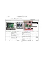
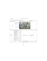
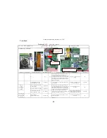
1
F10DA1-HEATSINK W/FAN-F4218
40-003650-01
1
Check the appearance of Heat Sink Module and ensure the
heat radiating blade is free of bruise. Place the fan on the jig
and put the left-side screw right above two support poles in
place.
Do not pinch the wries and do
not press the blade of the
portable fan.
Support jig.
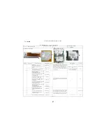
2
DATE CODE LABEL(month label)
63-000041-XX
1
Attach the month label on the fan onto the position shown
as per the figure.
NA
NA
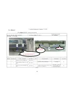
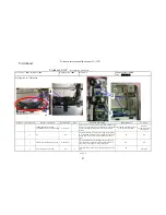
3
ODD ASS'Y
NA
1
Place the ODD on the support jig and fix with two
positioning poles in place.
NA
Support jig.
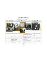
4
SCREW ISOT-M2X3L-SELF-
LOCKINGD3.5mm t=0.8mm-B4424H
41-721520-03
3
Place the M/B on the support jig and then lock three screws
to fix the fan by a-b-c sequence.
NA
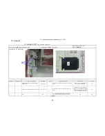
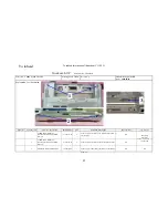
5
SCREW ISOT-M2X3L-SELF-
LOCKINGD3.5mm t=0.8mm-B4424H
41-721520-03
2
Lock two screws to fix the ODD on the M/B, as per the
figure.
NA
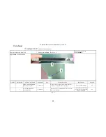
6
SCREW ISOT-M2X3L-SELF-LOCKING
∮
D3.5mm t=0.8mm-B4424H
41-721520-03
2
Assemble the Modem on the M/B and then lock two screw
to fix the Modem by a-b sequence, as per the figure.
NA
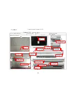
Explanation for illustration
PAGE:04
Electrical
Screwdriver/Torque: 1.5±
0.2Kgf-cm
Twinhead S.O.P
Document NO:TESOP587
Manufacturing Section: PE
Date: 2005.04.18
Working name
:
7003
Name of S.O.P
﹕
F10DA System Ass'y SOP
T
w
inhead International (Kunshan) CO.,LTD
T
w
inhead
4
a
b
c
2
6
5
1
3
b
28