background image


7


ENGLISH 

I

I

n

n

s

s

e

e

r

r

t

t

i

i

n

n

g

g


a

a

n

n

d

d


E

E

j

j

e

e

c

c

t

t

i

i

n

n

g

g


a

a


S

S

D

D


C

C

a

a

r

r

d

d


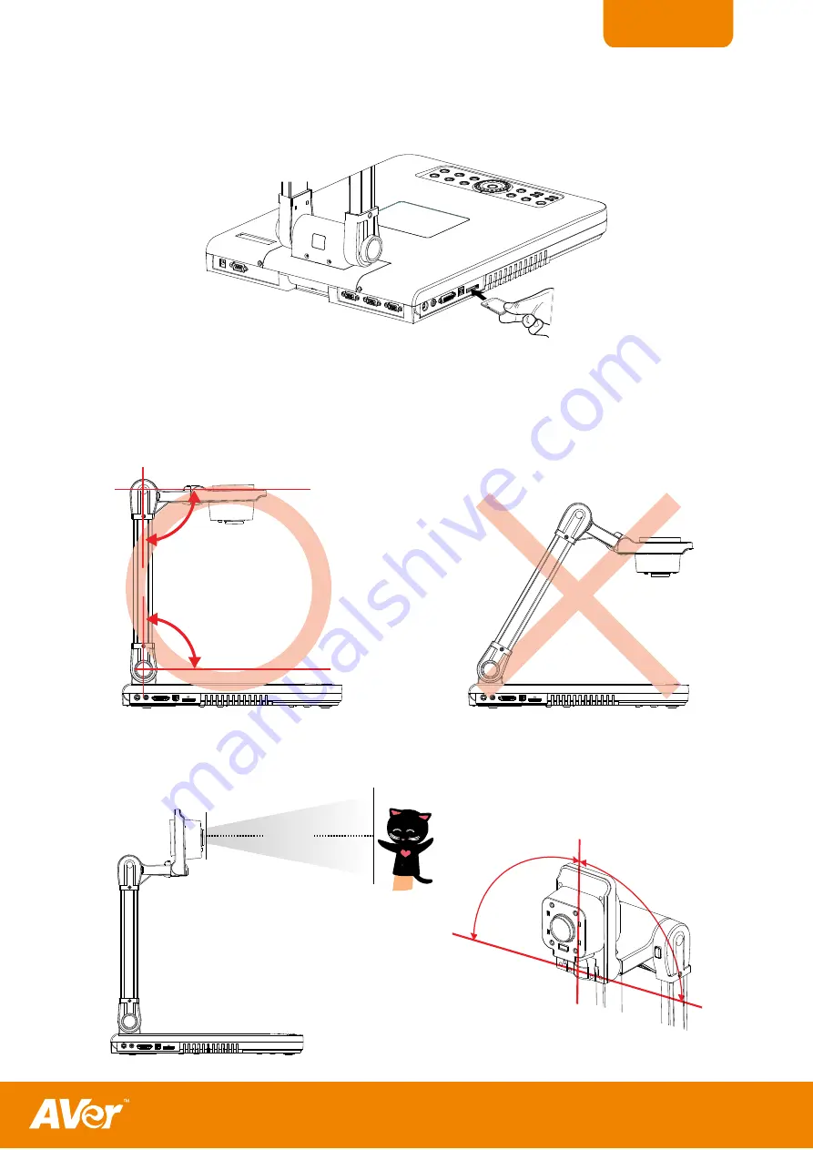
Insert the card with the label facing up until it reaches the end. To remove, pull the card out. The supported SD 
card capacity is from 16MB to 2GB. Make sure the card is formatted to FAT16.  automatically creates and 
stores the images in AVERJPG folder. 

SD card

(not supplied)

SD CA

RD

USB

DVI-

I OU

T

CVBS O

UT

S-VID

EO OU

T

RS-232

DC 12V

RGB IN 2

RGB IN 1

RGB OUT

IOIOI


S

S

e

e

t

t

t

t

i

i

n

n

g

g


U

U

p

p


S

S

P

P

B

B

3

3

5

5

0

0

+

+


This section provides useful tips on how to adjust the  to meet your needs. 

A

A

r

r

m

m


The arm must be unfolded fully in upright position. 

SD CARD

USB

DVI-I OUT

CVBS OUT

S-VIDEO OUT

90°

90°


SD CARD

USB

DVI-I OUT

CVBS OUT

S-VIDEO OUT

CVBS OU

DEO OU


C

C

a

a

m

m

e

e

r

r

a

a


H

H

e

e

a

a

d

d


The camera head can be folded up 90° and turned 90° to the left and right. 

To display an object more than 50cm 

away from the camera, unscrew the close-up lens. Do not forget to screw back the close-up lens afterwards. 

90°

90°

50cm

SD CARD

USB

DVI-I OUT

CVBS OUT

S-VIDEO OUT


Summary of Contents for AVerVision SPB350+

Page 1: ...either expressed or implied is made with respect to the contents of this documentation its quality performance merchantability or fitness for a particular purpose Information presented in this documentation has been carefully checked for reliability however no responsibility is assumed for inaccuracies The information contained in this documentation is subject to change without notice In no event ...

Page 2: ...g and Ejecting a SD Card 7 Setting Up SPB350 7 Arm 7 Camera Head 7 Overhead Light 8 Infrared Sensor 8 Light Box 8 Anti glare 8 Microscope Connection 9 Control Panel Light Color 9 Using the Infrared Remote Control 10 Touch Button Control Panel 12 Using AVerVision SPB350 as a Mass Storage 13 OSD Navigation Tree 14 Menu Functions 15 Technical Specifications 18 Using the RS 232 Interface 19 RS 232C Di...

Page 3: ... memory card When connected to a computer via USB connection and with the bundled software you can capture and save still images and video clips to your hard drive directly It also comes with a fully featured remote control P Pa ac ck ka ag ge e C Co on nt te en nt ts s Your AVerVision SPB350 package contains the following AVerVision SPB350 RM NK PROFILE TIMER ROTATE PIP SPLIT SCRN PRESENTER PLAYB...

Page 4: ...S Video output port 14 DVI I output port 15 USB port 16 SD card slot 17 DC 12V port 18 RS 232 port 19 RGB IN 2 port 20 RGB IN 1 port 21 RGB output port 22 Video output switch 23 Light box power button 24 Antitheft slot 1 4 5 3 2 11 6 8 9 7 10 Left Panel 15 12 14 16 13 SD CARD USB DVI I OUT CVBS OUT S VIDEO OUT SD CARD USB DVI I OUT CVBS OUT S VIDEO OUT Rear Panel 17 18 20 21 19 RS 232 DC 12V RGB I...

Page 5: ...amera RGB IN port or the captured images from the memory source on a VGA Mac monitor or LCD DLP projector Left Panel 1 2 3 4 5 SD CARD USB DVI I OUT CVBS OUT S VIDEO OUT Name Function 1 S VIDEO OUT Output the signal from the camera or the captured images from the memory source on TV or Video equipment 2 CVBS OUT RCA Composite Output the signal from the camera or the captured images from the memory...

Page 6: ...vice C Co on nn ne ec ct ti in ng g a a V VG GA A M Ma ac c M Mo on ni it to or r o or r L LC CD D D DL LP P P Pr ro oj je ec ct to or r Locate the RGB VGA input port of the display device and connect it to RGB OUT port of SPB350 If you are not sure please refer to the user manual of the device Make sure the Video Output switch is set to RGB RS 232 DC 12V RGB IN 2 RGB IN 1 RGB OUT IOIOI RGB cable ...

Page 7: ... Monitor with DVI interface DVI cable not supplied C Co on nn ne ec ct ti in ng g a a T TV V Locate the VIDEO yellow S VIDEO or SCART RGB input port of the TV or Video equipment i e VCR to record your presentation on a videotape and connect it to S VIDEO or CVBS OUT port of SPB350 If you are not sure please refer to the user manual of the TV or Video equipment Make sure the Video Output switch is ...

Page 8: ... RGB IN port is streamed to RGB and DVI I OUT ports only Press CAMERA PC button on the control panel or remote to switch to PC 1 or PC 2 RS 232 DC 12V RGB IN 2 RGB IN 1 RGB OUT IOIOI RGB cable Computer Laptop MAC Monitor Adapter not supplied C Co on nn ne ec ct ti in ng g a a C Co om mp pu ut te er r v vi ia a U US SB B C Co on nn ne ec ct ti io on n Locate the USB port of the computer or laptop a...

Page 9: ...12V RGB IN 2 RGB IN 1 RGB OUT IOIOI S Se et tt ti in ng g U Up p S SP PB B3 35 50 0 This section provides useful tips on how to adjust the SPB350 to meet your needs A Ar r m m The arm must be unfolded fully in upright position SD CARD USB DVI I OUT CVBS OUT S VIDEO OUT 90 90 SD CARD USB DVI I OUT CVBS OUT S VIDEO OUT CVBS OU DEO OU C Ca am me er ra a H He ea ad d The camera head can be folded up 9...
Page 10: ...nel of SPB350 to turn on and off light Use this to view negatives film and 35mm slides DO NOT place an object weighing more than 8kg on top of the light box LightBoxButton NegativeFilm Photos Document LightWeightObject 8Kg A An nt ti i g gl la ar re e The anti glare sheet is a special coated film that helps eliminate any glare that may be encountered while displaying very shiny objects or glossy s...

Page 11: ...ens from the camera head 4 Remove the microscope eyepiece from the microscope and connect it to the microscope adapter Then fasten the 3 bolts until the adapter secures the eyepiece Close up Lens Microscope Adapter optional Microscope We suggest using a microscope with an eye relief of 15 5mm or higher for better view 5 Screw the microscope adapter to the AVerVision camera head Then connect it to ...

Page 12: ...stment on the OSD main menu and sub menu See Menu Functions for more details Name Function 3 ENTER Make a selection in Playback mode and OSD menu Use this to quick zoom to 200 or back to 100 in Camera mode only 4 MENU Pull up and exit the OSD main menu and sub menu 5 Camera PC Switch between Camera and PC mode Camera mode displays the video signal from the built in camera PC mode displays the vide...

Page 13: ... to display the selected image in full screen Press MENU to display the Playback menu Select SLIDE SHOW to start or set the time interval between frames in second MEMORY SOURCE to select the image location between the built in memory or SD card and DELETE to permanently remove the selected image from the selected memory source 13 AUTO IMAGE Automatically adjust and set the white balance and exposu...

Page 14: ...back mode and OSD menu Use this to quick zoom to 200 or back to 100 in Camera mode only 5 AUTO IMAGE Automatically adjust and set the white balance and exposure setting 6 ROTATE Turn the image by 90 in Camera mode and 180 in full screen Playback mode 7 LAMP Turn the overhead light on off 8 CAP DEL Capture a still image in Camera mode The captured image is saved in the selected memory source at 160...

Page 15: ...en using the SPB350 as Mass Storage the following MUST be done 1 Select the memory source To select the memory source press MENU select SETTING MEMORY SOURCE EMBEDDED or SD and press ENTER then press MENU to exit 2 MUST set the USB CONNECTION as MASS STORAGE To set the USB connection type press MENU select SETTING USB CONNECTION MASS STORAGE and press ENTER then press MENU to exit 3 When MASS STOR...

Page 16: ...MORY 50 HZ 60 HZ FLICKER ON OFF NIGHT VIEW AUTO MANUAL FLICKER NIGHT VIEW 63 16 0 255 140 0 ENGLISH ESPAÑOL 日本語 繁體中文 LANGUAGE USB CAMER A MASS STORAGE USB CONNECTION NO YES PROFILE 1 PROFILE 2 PROFILE 3 PROFILE 1 PROFILE 2 PROFILE 3 SAVE 800 x 600 1024 x 768 1280 x 960 1600 x 1200 1280 x 720 1920 x 1080 HD 720p 60 Hz HD 1080p 60 Hz HD 720p 50Hz HD 1080p 50Hz 255 65 0 RED CAPTURE 5 SECS TEXT GRAPHI...

Page 17: ...s to select and turn on either SPOTLIGHT or VISOR Then press ENTER to make a selection Only one feature can be used at a time SPOTLIGHT overlays a frame on the presentation screen Selecting SHADE changes the opacity of the area outside the box from 0 50 and 100 COLOR to change the frame color from red green and blue and RESIZE to change the size of the frame To resize or move the frame around the ...

Page 18: ... exit IMAGE EXPOSURE WHITE BALANCE BRIGHTNESS CONTRAST RESOLUTION AUTO MANUAL FLICKER NIGHT VIEW SETTING IMAGE EXPOSURE Press and use or buttons to select between Auto Manual Flicker and Night View Then press ENTER to make a selection Select AUTO to automatically adjust the camera exposure to determine how much light is required MANUAL 21 54 0 SETTING IMAGE EXPOSURE MANUAL Use or buttons to manual...

Page 19: ...at and delete all the images saved in the memory source then press ENTER Please wait till the message FORMAT disappear to finish the process USB CONNECTION USB CAMERA MASS STORAGE SETTING USB CONNECTION Use or buttons to select the USB function between USB Camera an d Mass Storage USB Camera can be used as a computer webcam or with our bundled software as video recorder and capture still image Mas...

Page 20: ...e Balance Auto Manual Exposure Auto Manual Flicker Night View Theme Text Graphics High Frame Microscope Effect Color BW Negative Analog RGB Output SVGA XGA 1280 x 960 UXGA HD720 HD1080 DVI I supports reduced blanking only S Video Composite Video Output NTSC or PAL Image Capture Up to 240 Frames 2M Built In Memory 32MB NAND Flash Memory Optics Shooting Area 300mm x 225mm AVer Optical Zoom 20x Digit...

Page 21: ...2 is provided for the system integrator to be able to incorporate it with the system program R RS S 2 23 32 2C C D Di ia ag g r ra am m C Co on nn ne ec ct ti io on n SPB350 can be controlled using a PC through RS 232 connection RS 232 DC 12V RGB IN 2 RGB IN 1 RGB OUT IOIOI Computer RS 232 cable not supplied Laptop R RS S 2 23 32 2C C C Ca ab bl le e S Sp pe ec c Make sure the RS 232 cable matches...

Page 22: ...m Code Flicker 50Hz 0x00 0x00 0x00 0x5B Flicker 60Hz 0x00 0x01 0x00 0x5A Exposure Value 0x01 Value 0 95 0x00 1 WB Red Value 0x02 0x00 Value 0 255 1 WB Blue Value 0x02 0x01 Value 0 255 1 Brightness Value 0x03 Value 0 63 0x00 1 Contrast Value 0x04 Value 0 255 0x00 1 Rotate 0 degree 0x06 0x00 0x00 0x5D Rotate 90 degree 0x06 0x01 0x00 0x5C Rotate 180 degree 0x06 0x02 0x00 0x5F Rotate 270 degree 0x06 0...

Page 23: ...ng of the display output device 4 If you are using a notebook or computer you may have to switch the source to VGA 5 Make sure the TV RGB switch is properly set based on your display output There is no computer signal on the presentation screen When you turn on the computer it will auto detect the type of monitor you have During auto detection there won t be any display on your presentation screen...

Page 24: ...Limitations of Warranty AVer makes no warranties to any third party You are responsible for all claims damages settlements expenses and attorneys fees with respect to claims made against You as a result of Your use or misuse of the Product This warranty applies only if the Product is installed operated maintained and used in accordance with AVer specifications Specifically the warranties do not ex...

Reviews: