Avenview Cat5 User Manual Download Page 10

www.avenview.com 

10 


d.


Connect the Cable:

 Plug one ends of UTP cable to DVI-C5-S Transmitter’s “LINK IN/OUT” 

port and the other end to the DVI-C5-R Transceiver’s “LINK IN/OUT” port. The monitor 
connected to the Transceiver should now display and the “LINK” LED should turn green to 
indicate the DVI signal activation.   


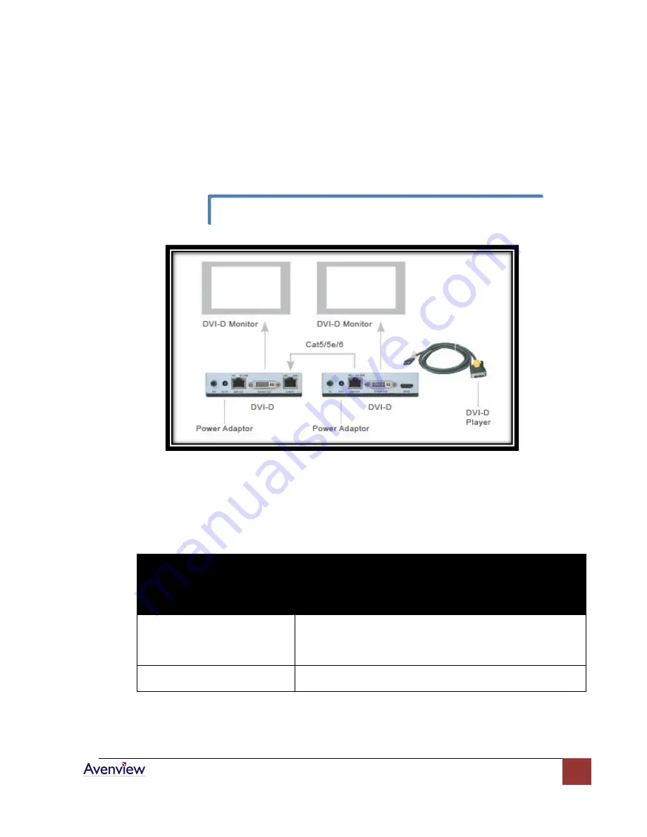
Installation Diagram of DVI-C5-S and DVI-C5-R 

e.


Extending Audio Signals:

 The DVI-C5-S Transmitter and DVI-C5-R Transceiver are not able to 

extend audio signals. Use a pair of Avenview AUD-RJ11 Audio Extenders with 4-wire phone 
cable and RJ11 connectors to extend the audio signal. 
 

General Troubleshooting 


Problem 
 

Possible Solution 

Off-Center Screen Image, Odd 
Colors or No Picture 


Try adjusting the brightness, sharpness, contrast, and color 
balance controls of your monitor. 


Try adjusting the centering and positioning controls of your 
monitor to position the picture on the screen.   

No Image 


Ensure that the monitor cable is securely fastened to the DVI 
and Monitor port. 


Use EQ control to adjust the video quality for best signal. 


Summary of Contents for Cat5

Page 1: ...in any form without the express written permission of Avenview Inc is strictly prohibited Disclaimer While every precaution has been taken in the preparation of this document Avenview Inc assumes no...

Page 2: ...C5 R Transceiver 4 Panel Description 5 DVI C5 S Transmitter and DVI C5 R Transceiver 5 Cable and Accessories 6 Installation and Operation 6 DVI C5 S Transmitter Installation 6 DVI C5 R Installation 7...

Page 3: ...The Cat5 DVI D Extender system is perfect for digital signage and public information display applications where crystal clear high resolution digital video needs to be shown without distance limitatio...

Page 4: ...ut c Built in one RJ45 port for system output which can be connected by Cat 5 5e 6 cable and send signal to System Receiver Transceiver DVI C5 R d Built in EQ control to adjust the video quality e Bui...

Page 5: ...www avenview com 5 Panel Description DVI C5 S Transmitter and DVI C5 R Transceiver...

Page 6: ...g the HDMI end to INPUT port of the Transmitter and the DVI D end to PC or DVD Player s DVD D video port Connect the power adapter to the 5VDC and plug into the power outlet c System Turn ON Turn on y...

Page 7: ...N the monitor b Device Connection Plug power adapter to DVI C5 R Transceiver the PWR LED and M1 LINK will turn ON The other LINK LED should turn off because there is no input of video signal from LINK...

Page 8: ...tting distance is the skew property of the cables Skew represents the difference in propagation delay between the fastest and slowest set of wire pairs A lower skew will mean a longer video transmitti...

Page 9: ...s to the Cat 5 5e 6 cable must be made to the EIA 568B specifications 1 Orange White 2 Orange 3 Green White 4 Blue 5 Blue White 6 Green 7 Brown White 8 Brown The EIA TIA definition of 568B in the pin...

Page 10: ...R Transceiver are not able to extend audio signals Use a pair of Avenview AUD RJ11 Audio Extenders with 4 wire phone cable and RJ11 connectors to extend the audio signal General Troubleshooting Probl...

Page 11: ...y using additional DVI C5 R Transceivers it is possible to extend the system almost indefinitely to remote DVI D displays Installation Diagram of Multiple Transceivers Ensure that common grounding is...

Page 12: ...rt DVI D Transceiver Input HDMI DVI HDMI Connector RJ45 x 1 Output DVI Female x 1 RJ45 x 1 DVI Female x 1 RJ45 x 1 Max Distance and Resolution With each cascading length 80m 275ft 800 x 600 50m 175ft...

Page 13: ...www avenview com 13...

Reviews: