background image

English - 21

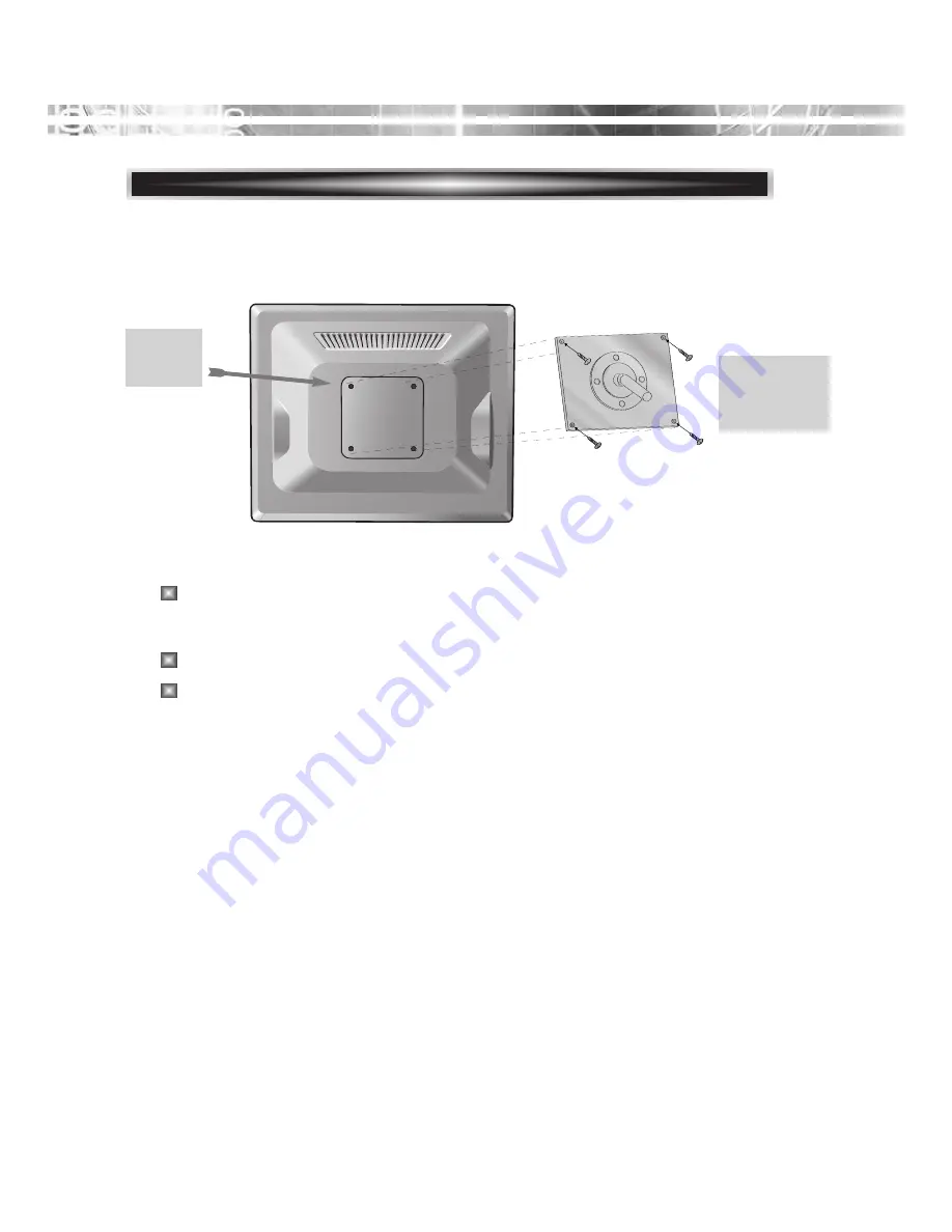
ATTACHING THE MONITOR WITH THE ARM-STAND(OPTION)

Tighten up screws at the locations
indicated by arrows.

Support
stand 

Surface for
stand
installation

This monitor’s installation surface is compatible with various kinds
of VESA standard stands. 

Hole spacing : 100x100 mm

Screw Length : 8~12 mm 

Summary of Contents for MON-LCD19BL-CCTV

Page 1: ...MON LCD19BL CCTV Reference Manual...

Page 2: ......

Page 3: ...warnings and instructions marked on the monitor IMPORTANT SAFEGUARDS 12 For added protection for this monitor during a lightning storm or when it is left unattended and unused for long periods of tim...

Page 4: ...ate the receiving antenna Increase the separation between the equipment and receiver Connect the equipment to an outlet on a circuit different from that to which the receiver is connected Consult the...

Page 5: ...Setup 3 Stand Assembling Procedures 3 Connecting the 15 Pin Signal Cable and Power Cord 4 Connecting the others 5 Operation Adjustment 6 Specifications 16 Factory Preset Timings 18 Monitor rotation O...

Page 6: ...eference First please check that the contents of the box corresponds with the following checklist TFT LCD monitor Power cord RCA Cable 15 pin signal cable User s guide Audio Cable Optional DVI Cable o...

Page 7: ...perature RGB gain value for the best possible screen color and intensity Press the menu button and activate the Self Diagnosis menu to determine whether your monitor is functioning normally not receiv...

Page 8: ...h the metal protrusion from the bottom of the monitor s main body Tighten the screw fully at the bottom of the stand by turning it clockwise three to four turns l After fully tightening the screw bend...

Page 9: ...DVI cable to the output port of the video card in your computer and monitor Optional Connect the audio cable to the output port of the sound card in your computer Optional Plug the DC jack into the D...

Page 10: ...tor to AUDIO INPUT port on the rear of the monitor ex Computer CD Player 3 Plug the connector to AUDIO OUTPUT port on the rear of the monitor ex Speaker Headphone 2 1 3 1 Turn on monitor 2 Choose VIDE...

Page 11: ...e the OSD screen off selects input source and after pressing SOURCE sets menu functions Menu 5 Turns the OSD window on Turns the OSD On Screen Display window off and moves from sub menu to top menu in...

Page 12: ...indow and opens the function window for the selected icon While the OSD screen off selects input source and after pressing SOURCE sets menu functions Menu 5 Turns the OSD window on Turns the OSD On Sc...

Page 13: ...on Use up down button to select the main menu Use SOURCE button to select the sub menus on the right Use up down buttons to select sub menu function Press SOURCE button then using left right buttons y...

Page 14: ...tton you can use the best displayperformance fit for a current mode Analog MODE Selects signal in order ANALOG DIGITAL VIDEO When there is no OSD if you press this UP MUTE button you can turns the sou...

Page 15: ...Adjust the CLOCK control Perform the H POSITION Perform the Auto tracking Is the H SIZE proper Is the noise displayed on the screen Adjust the CLOCK until the screen is cleared Is the noise displayed...

Page 16: ...n the image of characters Adjust the width horizontal size of the screen image Phase Clock Adjust the display image quality if the screen proceed to scaling up Sharpness Choose automatically the prope...

Page 17: ...eft or right and vertically up or down OSD H V Pos Adjust the display OSD time OSD Timer Select input signal source D SUB DVI CVBS Signal Source Select powerlight mode PC Game Movie Mode Reset the scr...

Page 18: ...Saturation Adjust the hues of image Hue Color OSD MISC Select input signal source D SUB DVI CVBS Signal Source Select powerlight mode PC Game Movie Mode Reset the screen to the Factory Preset Display...

Page 19: ...English 14 SOUND Turn the audio sound on or off Sound Increase or decrease audio volume Volume OSD...

Page 20: ...of range or None support No Signal screen is displayed when the D Sub signal connector is connected but the status of the monitor is on DPMS mode Out of Range screen is displayed when the applied fre...

Page 21: ...Colors Display Area 337 9 mm x 270 3 mm PC Input Signal Sync H V separate TTL Video 15 pin D sub Analog RGB DVI D Optional AV Input Signal VIDEO BNC Input Output AUDIO RCA Left Right Input Stereo Min...

Page 22: ...IDEO BNC Input Output AUDIO RCA Left Right Input Stereo Mini Jack Input Output Speaker Max Output 4W Left 2W Right 2W Plug and Play VESA DDC Compatible Power Source DC 12V 3 33A Power Consumption 26 W...

Page 23: ...ced SXGA 1280 X1024 60Hz 64 0 60 Non interlaced SXGA 1280 X1024 75Hz 80 0 75 Non interlaced SXGA 1152 X 864 75Hz 67 5 75 Non interlaced SXGA 1280 X 960 60Hz 60 0 60 Non interlaced EGA 640 X 350 70Hz 3...

Page 24: ...with VGA card that is compatible with screen rotation function in Window XP environment This product is not accompanied by software which supports the screen rotation function 1 Lean the monitor s ma...

Page 25: ...Remove the four screws connecting the stand and the body and the stand is disassembled Turn off the monitor and pull out the power cable Place a cushion or a soft cloth on the floor and put the produc...

Page 26: ...AND OPTION Tighten up screws at the locations indicated by arrows Support stand Surface for stand installation This monitor s installation surface is compatible with various kinds of VESA standard sta...

Page 27: ...connected Check if the signal cable is suitable to the video card Adjust Clock or H V Center to get the proper image Keep the devices that may cause electrical interference away from the monitor See...

Page 28: ...erminal is properly connected Check if the video cable is correctly connected to the computer and set to the video mode Adjust the Saturation or Hue on the OSD Menu in the video mode Adjust the Sharpn...

Reviews: