


TESTING AND TEST SET
-
UP
Page 14
The H
-
1, H
-
1 (light pedal) and H
-
1
-
A Controlair
Valve can be tested after repair using the test
arrangement shown below.
Pressure control valves of this nature should be
tested for the following:
1.
Function
2.
Pressure Range
3.
Leakage
4.
Flow Capacity
5.
Response
The adjustment affecting these points has been
described in the previous section. General
instructions for accomplishing the five tests above
are as follows.
1. Function:
The H
-
1 and H
-
1
-
A type Controlair
Valves are spring returned pedal actuated 3
-
way pressure graduating valves. A pedal
actuates the valve to increase, decrease or
maintain graduated air pressure to a separate
delivery line. This function should be checked
using test arrangement shown.
2. Pressure Range:
Supply pressure at
“
IN
”
port
will be delivered as graduated pressure to
“
Out
”
port delivery line depending on value of
control spring being used and pedal position. In
pedal release position the out delivery line is
connected to exhaust. Depressing the pedal
actuates the graduating control portion to
deliver graduated pressure to the out delivery
line. See
“
Adjustments
”
to adjust valve. After
valve is adjusted, check that the zero and
maximum pressure ranges are generated in
delivery line as per
“
Identity Schedule
”.
3. Leakage:
Set supply pressure to 20 psi above maxi-
mum delivery pressure of valve being tested. Using
soap solution, coat the valve at pipe bracket and
spring housing parting lines. No leakage is permitted
in any pedal position.
A. On all valves with spring ranges less than 100 psi,
set supply lines pressure to 100 psi. Depress pedal
to full travel position and hold. Close valve in sup-
ply line to
“
IN
”
port and valve in delivery line from
“
OUT
”
delivery line pressure gage. A pressure drop
of no more than 2 psi in 30 seconds is permitted.
B. On all valves with spring ranges 100 psi and above,
set supply line pressure to 100 psi. Depress pedal
to deliver 95 psi to delivery line from
“
OUT
”
port.
Close valve in supply line to
“
IN
”
port and valve in
delivery line from
“
OUT
”
port to trap the supply
pressure at the valve. Observe the
“
OUT
”
delivery
line pressure gage. A pressure drop of no more
than 2 psi in 30 seconds is permitted.
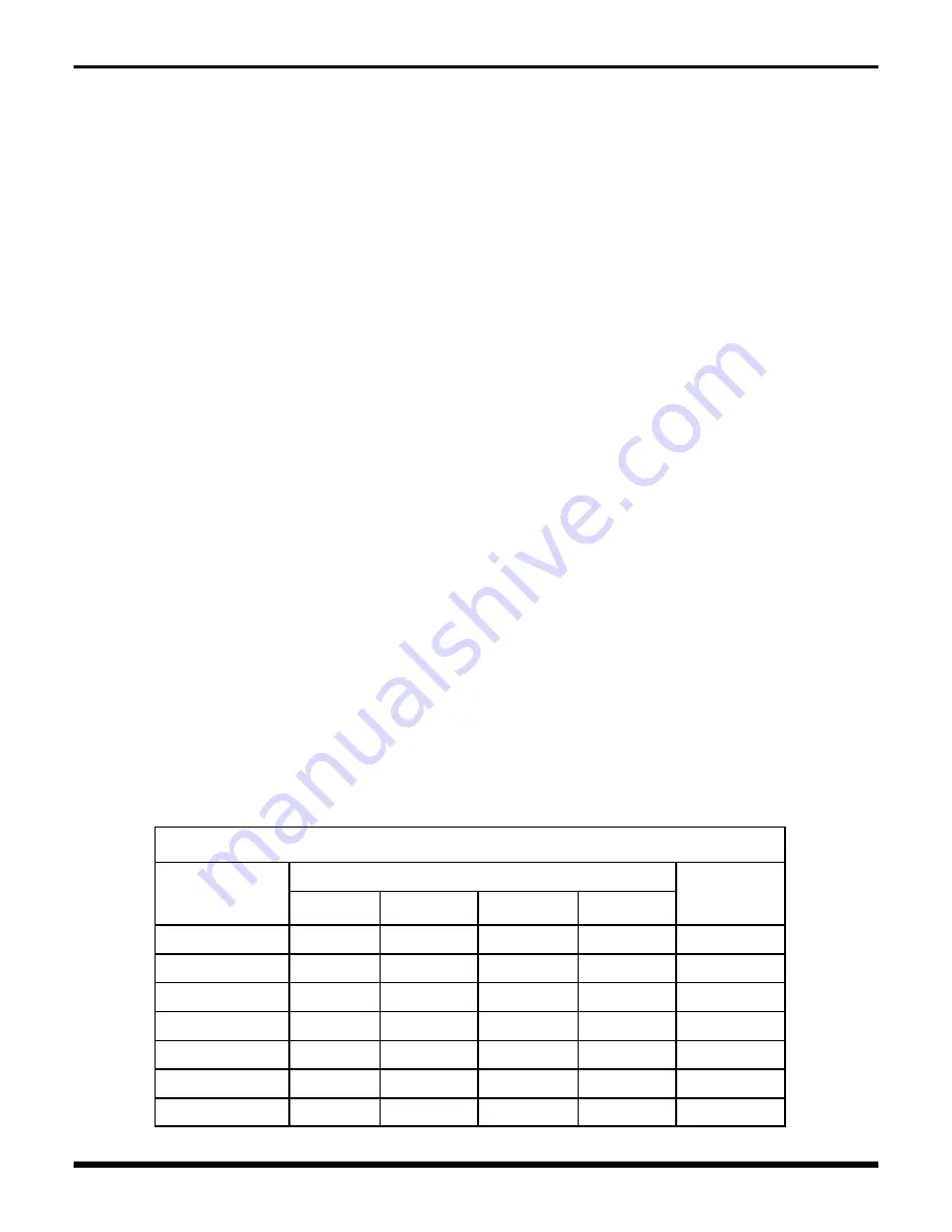
4. Flow Capacity:
Set supply line pressure to 100 psi
regardless of control spring rating of valve. Depress
pedal to full travel position. The delivery volume or
volumes from
“
OUT
”
port should be inflated with time
limits shown on Table 1. Release pedal quickly from
full travel position to release position. The delivery vol-
ume or volumes connected to
“
OUT
”
port should be
“
exhausted
”
within time limits shown in Table 1.
5. Response:
Depress pedal to full travel position. Fully
open the test valve at delivery volume from
“
OUT
”
port. Observe the delivery pressure gage. A pressure
drop of no more than 3 psi is permitted. Release pe-
dal.
Table 1
Flow Capacity Tests –
Port
“
OUT
”
Valve Setting PSI
Test Ranges and Time
Test Volume
Cu. In.
Fill PSI
Maximum
Time
-
Sec.
Exhaust
PSI
Maximum
Time
-
Sec.
0
-
30
0
-
15
2
0
-
15
2
450
0
-
35
0
-
15
2
0
-
15
2
450
0
-
65
0
-
50
1
50
-
10
2
225
0
-
100
0
-
50
1
50
-
10
2
225
0
-
125
0
-
50
1
50
-
10
2
225
0
-
150
0
-
50
1
50
-
10
2
225
0
-
175
0
-
50
1
50
-
10
2
225


