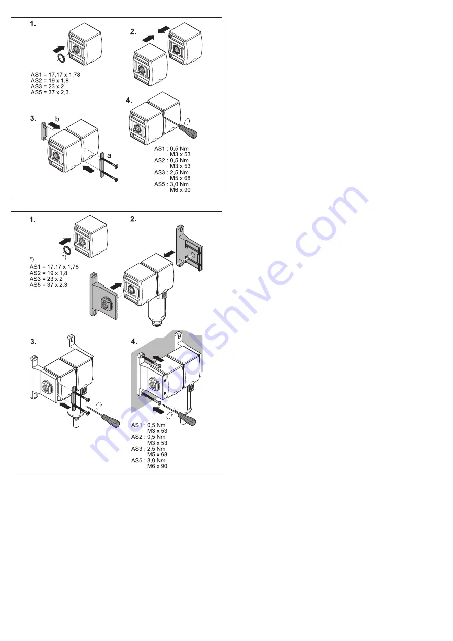
Fig. 17: Unión con juego de unión W04
Fig. 18: Unión y fijación con juego de unión W05
AVENTICS™
AS1 / AS2 / AS3 / AS5 | R412013433-BAL-001-AI | Español
43
Page 1: ...ventil Befüllventil BAV SOV SSV SSU 3 2 shut off valve and directional valve filling valve BAV SOV SSV SSU Vanne d arrêt et distributeur 3 2 vanne de mise en pression BAV SOV SSV SSU Valvola di blocco e valvola 3 2 valvola di riempimento progressivo BAV SOV SSV SSU Válvula de cierre de 3 2 vías y válvula distribuidora de 3 2 vías válvula de llenado BAV SOV SSV SSU 3 2 avstängningsventil och riktni...
Page 2: ... 2 Wegeventil SOV Pneumatisch betätigt 5 5 4 1 Anschließen 5 5 5 2 2 Wegeventil bzw 3 2 Wegeventil SOV Elektrisch betätigt 5 5 5 1 Leitungsdose mit Anschluss Form C montieren 5 5 5 2 Verbindungskabel mit Anschluss M12 anschließen 5 5 5 3 Ausgewähltes Vorsteuerventil DO16 montieren 5 5 5 4 Adapterplatte AS CNOMO montieren 5 5 5 5 Vorsteuerventil DO30 montieren 5 5 5 6 Spule für Ex Bereich montieren...
Page 3: ...renzen ein Verwenden Sie als Medium ausschließlich Druckluft Das Produkt ist ein technisches Arbeitsmittel und nicht für die private Verwen dung bestimmt Die bestimmungsgemäße Verwendung schließt auch ein dass Sie diese Anlei tung und insbesondere das Kapitel Sicherheitshinweise vollständig gelesen und verstanden haben siehe Sicherheitshinweise 2 2 ATEX Die mechanischen Wartungseinheiten Wartungsg...
Page 4: ...nicht beschädigt werden und niemand darüber stolpern kann Das Produkt darf nicht in aggressiver Umgebungsluft z B Lösungsmitteldämpfe betrieben werden 3 Lieferumfang 1 Ventil laut Bestellung Bedienungsanleitung Montageanleitung Zusätzlich beim 3 2 Wegeventil mit Endlagenabfrage AS3 AS5 Sensor vormontiert 4 Zu diesem Produkt 3 2 Absperrventile 3 2 Wegeventile und Befüllventile AS sind Komponenten v...
Page 5: ...ung und befestigen Sie die Adern an den Klemmen 4 Schließen Sie die Leitungsdose 5 Legen Sie die Dichtung h auf die Spule e 6 Stecken Sie die Leitungsdose i auf die Kontakte der Spule e und befestigen Sie die Leitungsdose mit der Schraube k 5 5 6 Spule für Ex Bereich montieren Siehe Abb 8 1 Setzen Sie das Vorsteuerventil c auf die Adapterplatte b und schrauben Sie es mit den mitgelieferten Schraub...
Page 6: ...en bevor Sie das Gerät ausbauen 8 Entsorgung Entsorgen Sie das Produkt und das Kondensat nach den nationalen Bestimmun gen Ihres Landes 9 Erweiterung und Umbau VORSICHT Verletzungsgefahr bei Demontage oder Austausch unter Druck oder Span nung Demontage oder Austausch unter Druck oder anliegender elektrischer Span nung kann zu Verletzungen führen und das Produkt oder Anlagenteile beschä digen 1 Sch...
Page 7: ...ose mit Anschluss Form C montieren Serie AS1 AS2 AS3 AS5 2 1 b a c Abb 4 2 2 Wegeventil bzw 3 2 Wegeventil SOV Elektrisch betätigt Verbin dungskabel mit Anschluss M12 anschließen Serie AS1 AS2 AS3 AS5 Abb 5 2 2 Wegeventil bzw 3 2 Wegeventil SOV Elektrisch betätigt Ausgewähltes Vorsteuerventil DO16 montieren nicht für explosionsgefährdete Bereiche Serie AS1 AS2 AS3 AS5 Abb 6 2 2 Wegeventil bzw 3 2 ...
Page 8: ...nstellbar Serie AS2 AS3 P1 Betriebsdruck P2 Ausgangsdruck t Zeit tx Umschaltzeitpunkt Px Umschaltdruck a Umschaltdruck Px einstellen b Befüllzeit über Stellschraube Drossel einstellbar siehe auch Kapitel Pneuma tisch betätigt Befüllzeit einstellen P1 P2 t P P2 P1 tx a a a Abb 11 Befüllventil SSV mit elektrischer Vorrangschaltung Befüllzeit über Stell schraube Drossel einstellbar Serie AS2 AS3 AS5 ...
Page 9: ... wechseln Serie AS1 AS2 AS3 AS5 Abb 15 Befestigung mit Befestigungsplatte W01 Abb 16 Verblockung und Befestigung mit Befestigungsbügel W03 Abb 17 Verblockung mit Verblockungssatz W04 Abb 18 Verblockung und Befestigung mit Verblockungssatz W05 AVENTICS AS1 AS2 AS3 AS5 R412013433 BAL 001 AI Deutsch 9 ...
Page 10: ...ectional valve pneumatically operated 12 5 4 1 Connecting 12 5 5 SOV 2 2 directional or 3 2 directional valve electrically operated 13 5 5 1 Mount electrical connector with C shape connection 13 5 5 2 Attach connecting cable to connection M12 13 5 5 3 Mount selected DO16 pilot valve 13 5 5 4 Mounting transition plate AS CNOMO 13 5 5 5 Mounting pilot valve DO30 13 5 5 6 Mounting coil for explosive ...
Page 11: ...instructions see Notes on safety 2 2 ATEX If operated as intended mechanical maintenance units equipment have no inherent potential source of ignition and no internal explosive atmosphere They are not labelled according to ATEX Directive 2014 34 EU Manufacturer declarations may be requested via your service partner It is imperative that you comply with the set up regulations for ex compo nents e g...
Page 12: ...rent requirements via various coils and plates 3 2 directional valves with end position detection are used to detect the position of the control piston via a sensor An output signal is supplied on the connected sensor when the valve is in its inactive position 2 3 exhaust Sensor switching is also visible on the front plate on AS3 and rear plate on AS5 Filling valves permit controlled application o...
Page 13: ... without a SSU filling unit that the cylinders are in their end position or that no danger can emit from those not in end position During commissioning 1 Let the product acclimatize for several hours before commissioning other wise water may condense in the housing 2 Check that all the electrical and pneumatic connections are allocated or closed Only commission fully installed products 5 6 Filling...
Page 14: ...nging parts 2 Protect the system against being restarted CAUTION Danger of burns The surfaces of adjacent system components can become hot during opera tion u Let the system component cool off before disassembling it 9 1 Change flow direction See Fig 14 No conversion is necessary on the AS1 series The right left flow ver sion has a separate order number On delivery the flow direction is from left ...
Page 15: ...ting cable with M12 connection Series AS1 AS2 AS3 AS5 Fig 5 SOV 2 2 directional or 3 2 directional valve electrically operated Mount selected DO16 pilot valve not for explosive areas Series AS1 AS2 AS3 AS5 Fig 6 SOV 2 2 directional or 3 2 directional valve electrically operated Mount AS CNOMO transition plate Series AS1 AS2 AS3 AS5 MD 0 4 Nm Fig 7 SOV 2 2 directional or 3 2 directional valve elect...
Page 16: ...illing time adjustable via adjustment screw throttle see also chapter Pneu matically operated Adjust filling time P1 P2 t P P2 P1 tx a a a Fig 11 SSV filling valve with electric priority circuit filling time adjustable via ad justment screw throttle Series AS2 AS3 AS5 P1 operating pressure P2 output pressure t time tx switchover time a electrically triggered switching point P1 P2 t P P2 P1 tx a a ...
Page 17: ...te W01 Fig 16 Block assembly and mounting with mounting clip W03 Fig 17 Block assembly with W04 block assembly kit Fig 18 Block assembly and mounting with W05 block assembly kit AVENTICS AS1 AS2 AS3 AS5 R412013433 BAL 001 AI English 17 ...
Page 18: ...ordement 21 5 5 Distributeur 2 2 ou distributeur 3 2 SOV Commande électrique 21 5 5 1 Montage du connecteur avec orifice en forme C 21 5 5 2 Raccordement du câble de connexion au raccord M12 21 5 5 3 Montage du distributeur pilote DO16 sélectionné 21 5 5 4 Montage de la plaque d adaptation AS CNOMO 21 5 5 5 Montage du distributeur pilote DO30 21 5 5 6 Montage de la bobine pour atmosphère explosibl...
Page 19: ...la machine ou l installation à laquelle il a été destiné Respecter les conditions de fonctionnement et les limites de puissance figurant dans les données techniques Comme fluide utiliser uniquement de l air compri mé Le produit est un outil de travail technique non destiné à un usage dans le do maine privé L utilisation conforme inclut aussi le fait d avoir lu et compris la présente notice dans so...
Page 20: ...l de drogues ou de médicaments divers pouvant altérer leur temps de réaction La garantie n est plus valable en cas de montage incorrect Ne surcharger en aucun cas le produit de manière mécanique de par une utili sation non conforme Les avertissements et indications concernant le produit doivent rester lisibles et ne pas être recouverts par de la peinture ou autre 2 7 Consignes de sécurité selon le...
Page 21: ...distributeur pilote DO30 b sur la plaque d adaptation et le visser à fond avec les vis fournies d 2 Mettre la bobine e et la rondelle f sur l axe du distributeur b et les fixer avec l écrou moleté g 3 Ouvrir le connecteur faire passer le câble dans n m l et l introduire dans l ouverture puis fixer les fils aux bornes 4 Fermer le connecteur 5 Poser le joint h sur la bobine e 6 Enficher le connecteu...
Page 22: ...tage ou de remplacement sous pression ou sous tension Le démontage ou remplacement sous pression ou sous tension électrique en présence peut provoquer des blessures et endommager le produit ou des par ties de l installation 1 Mettre la partie pertinente de l installation hors pression et hors tension avant de démonter le produit ou de remplacer des pièces 2 Protéger l installation de toute remise ...
Page 23: ...érente Température min max du fluide ambiante 10 C 50 C D autres données techniques figurent dans le catalogue en ligne sur le site www aventics com pneumatics catalog 12 Annexe Figures la vue peut varier en fonction de la série Fig 1 Distributeur 3 2 BAV à commande mécanique régler la position de la vanne 1 III fermer la vanne 1 I IV série AS1 AS2 AS3 AS5 a b c d 2 1 Fig 2 Distributeur 3 2 SOV à ...
Page 24: ... série AS2 AS3 AS5 a P1 t P P2 0 5 x P1 50 P2 P1 tx P2 Fig 9 Vanne de mise en pression SSV à commande pneumatique série AS1 AS2 AS3 AS5 P1 pression de service P2 pression de sortie t durée tx point de commu tation a temps de remplissage réglable via une vis de réglage limiteur 3 1 2 a b P1 P2 t P P2 P1 tx Px Fig 10 Vanne de mise en pression SSV à commande pneumatique temps de remplissage et pressi...
Page 25: ...uit prioritaire pneumatique temps de remplissage réglable via une vis de réglage limiteur série AS2 AS3 AS5 P1 pression de service P2 pression de sortie t durée tx point de commu tation a point de commutation déclenché pneumatiquement Fig 13 Unité de mise en pression SSU série AS1 AS2 AS3 AS5 I II Fig 14 Modification du sens du débit échanger les couvercles du boîtier sé rie AS1 AS2 AS3 AS5 Fig 15...
Page 26: ...7 Blocage montage en batterie avec kit de montage en batterie W04 Fig 18 Blocage montage en batterie et fixation avec kit de montage en batterie W05 AVENTICS AS1 AS2 AS3 AS5 R412013433 BAL 001 AI Français 26 ...
Page 27: ...egamento 30 5 5 Valvola 2 2 o valvola 3 2 SOV ad azionamento elettrico 30 5 5 1 Montaggio del connettore con l attacco di forma C 30 5 5 2 Fissaggio del cavo di collegamento al raccordo M12 30 5 5 3 Montaggio della valvola pilota DO16 prescelta 30 5 5 4 Montaggio della piastra di adattamento AS CNOMO 30 5 5 5 Montaggio della valvola pilota DO30 30 5 5 6 Montaggio della bobina per zona Ex 30 5 6 Va...
Page 28: ...rivato L uso a norma comprende anche la lettura e la comprensione completa di queste istruzioni ed in particolar modo del capitolo Avvertenze di sicurezza vedi Indi cazioni di sicurezza 2 2 ATEX Gli apparecchi di manutenzione gruppi di trattamento meccanici sono conce piti secondo le prescrizioni senza una potenziale fonte combustibile propria e privi di atmosfera esplosiva interna Non sono quindi...
Page 29: ...rizione del prodotto Le valvole di blocco 3 2 le valvole 3 2 e le valvole di riempimento progressivo AS sono componenti di gruppi di trattamento Le valvole di blocco 3 2 servono all intercettazione meccanica o pneumatica dell aria compressa Le valvole 3 2 che consentono di controllare elettricamente l aria compressa possono essere adattate alle varie esigenze mediante diverse bobine e piastre Le v...
Page 30: ...h ATTENZIONE Aumento improvviso della pressione durante la messa in funzione Se non viene utilizzata nessuna unità di riempimento SSU durante la messa in funzione l impianto è sottoposto a pressione improvvisa Per questo possono verificarsi movimenti dei cilindri a scatti e pericolosi u Assicurarsi che durante la messa in funzione di un impianto senza unità di riempimento SSU i cilindri si trovino...
Page 31: ...zione ATTENZIONE Pericolo di ferimento dovuto allo smontaggio o alla sostituzione in pressione o in tensione elettrica Lo smontaggio o la sostituzione in pressione o in tensione elettrica può provo care ferimenti e danneggiare il prodotto o parti dell impianto 1 Togliere l alimentazione elettrica e pneumatica della parte dell impianto ri levante prima di smontare il prodotto o sostituire dei compo...
Page 32: ...taggio del connettore con raccordo a forma di C Serie AS1 AS2 AS3 AS5 2 1 b a c Fig 4 valvola 2 2 o valvola 3 2 SOV ad azionamento elettrico collegamento del cavo di collegamento con raccordo M12 Serie AS1 AS2 AS3 AS5 Fig 5 valvola 2 2 o valvola 3 2 SOV ad azionamento elettrico montaggio della valvola pilota DO16 prescelta non per aree a rischio di esplosio ne Serie AS1 AS2 AS3 AS5 Fig 6 valvola 2...
Page 33: ...d uscita t tempo tx punto di com mutazione Px pressione di commutazione a Regolazione della pressione di commutazione Px b Tempo di riempimento regolabile tramite vite di regolazione strozzamento vedere anche il capitolo Azionamento pneumatico Impostazione del tempo di riempimento P1 P2 t P P2 P1 tx a a a Fig 11 Valvola di riempimento progressivo SSV con circuito elettrico prioritario di riempimen...
Page 34: ...po Serie AS1 AS2 AS3 AS5 Fig 15 Fissaggio con piastra di fissaggio W01 Fig 16 Montaggio in batteria e fissaggio con staffa di fissaggio W03 Fig 17 Montaggio in batteria con set per il montaggio in batteria W04 Fig 18 Montaggio in batteria e fissaggio con set per il montaggio in batteria W05 AVENTICS AS1 AS2 AS3 AS5 R412013433 BAL 001 AI Italiano 34 ...
Page 35: ... SOV de 3 2 vías de accionamiento neumático 38 5 4 1 Conexión 38 5 5 Válvula distribuidora de 2 2 vías o SOV de 3 2 vías de accionamiento eléctrico 38 5 5 1 Montaje del conector eléctrico con conexión de forma C 38 5 5 2 Conexión del cable de unión con conexión M12 38 5 5 3 Montaje de la válvula de pilotaje previo DO16 seleccionada 38 5 5 4 Montaje de la placa adaptadora AS CNOMO 38 5 5 5 Montaje ...
Page 36: ...quina o instalación El producto no debe ponerse en funcionamiento hasta que esté mon tado en la máquina instalación para la que fue concebido Respete las condiciones de servicio y los límites de potencia mencionados en los datos técnicos Como medio únicamente se puede utilizar aire comprimido El producto es un material de trabajo técnico y no está diseñado para uso priva do La utilización conforme...
Page 37: ...mitido modificar ni transformar el producto Las personas que montan manejan y desmontan productos de AVENTICS o realizan su mantenimiento no deben encontrarse bajo la influencia del alco hol drogas o medicamentos que pudieran afectar a la capacidad de reacción La garantía prescribe en el caso de un montaje defectuoso En ninguna circunstancia debe someter el producto a cargas no admisibles Las adve...
Page 38: ...amiento auxiliar manual d 5 5 2 Conexión del cable de unión con conexión M12 Véase la fig 4 u Enrosque el conector M12 a en el conector eléctrico b Sobre el funcionamiento Al aplicar tensión a la bobina la válvula conmuta a paso 1 2 Si hay presión en P1 la válvula se puede conectar manualmente mediante el accionamiento auxiliar manual c 5 5 3 Montaje de la válvula de pilotaje previo DO16 seleccion...
Page 39: ...n adecuados para que no penetre ningún producto de limpieza en el sistema No utilice nunca disolventes ni detergentes agresivos Limpie el producto ex clusivamente con un paño humedecido Para ello utilice únicamente agua y en caso necesario un detergente suave No utilice aparatos limpiadores de alta presión para la limpieza No utilice aire comprimido para limpiar purgar las unidades o aparatos de p...
Page 40: ...os empalmes 11 Datos técnicos Los valores correspondientes a presión máxima admisible rango de temperatura y conexión por rosca están indicados en los productos Generalidades Posición de montaje Indiferente Temperatura del medio ambiente mín máx 10 C 50 C Puede consultar más datos técnicos en el catálogo online en www aventics com pneumatics catalog 12 Anexo Figuras la vista varía en función de la...
Page 41: ...bobina para zona con riesgo de explosión Serie AS2 AS3 AS5 a P1 t P P2 0 5 x P1 50 P2 P1 tx P2 Fig 9 Válvula de llenado SSV de accionamiento neumático Serie AS1 AS2 AS3 AS5 P1 presión de servicio P2 presión de salida t tiempo tx momento de con mutación a el tiempo de llenado se puede ajustar con el tornillo de ajuste estrangulador 3 1 2 a b P1 P2 t P P2 P1 tx Px Fig 10 Válvula de llenado SSV de ac...
Page 42: ...V de conexión neumática de prioridad tiempo de llenado ajustable con el tornillo de ajuste estrangulador Serie AS2 AS3 AS5 P1 presión de servicio P2 presión de salida t tiempo tx momento de con mutación a punto de conmutación activado neumáticamente Fig 13 Unidad de llenado SSU Serie AS1 AS2 AS3 AS5 I II Fig 14 Modificación de la dirección del caudal Cambio de la tapa de la carcasa Serie AS1 AS2 A...
Page 43: ...Fig 17 Unión con juego de unión W04 Fig 18 Unión y fijación con juego de unión W05 AVENTICS AS1 AS2 AS3 AS5 R412013433 BAL 001 AI Español 43 ...
Page 44: ... styrd 46 5 4 3 2 ventil SOV pneumatiskt styrd 46 5 4 1 Anslutning 46 5 5 2 2 ventil resp 3 2 ventil SOV elektriskt styrd 47 5 5 1 Montera anslutningskontakt med anslutning form C 47 5 5 2 Ansluta anslutningskabel med M12 kontakt 47 5 5 3 Montera utvald pilotventil DO16 47 5 5 4 Montera adapterplatta AS CNOMO 47 5 5 5 Montera pilotventil DO30 47 5 5 6 Montera spole för Ex område 47 5 6 Mjukstartve...
Page 45: ...ändning innebär också att du har läst och förstått denna bruksanvisning och speciellt kapitlet Säkerhetsföreskrifter se Säkerhetsföreskrifter 2 2 ATEX De mekaniska luftbehandlingsenheterna produkterna har vid avsedd användning ingen egen potentiell antändningskälla och ingen intern explosionsfarlig atmosfär De saknar märkning enligt ATEX direktiv 2014 34 EU Tillverkarförklaringar tillhandahålls av...
Page 46: ... 2 ventiler som möjliggör elektrisk koppling av tryckluft kan anpassas till varierande krav med olika spolar och plattor 3 2 ventiler med ändlägesindikering kan dessutom visa styrkolvens läge via en sensor En utgångssignal ligger an på den anslutna sensorn när ventilen befinner sig i opåverkat läge 2 3 avluftning Sensorns omkoppling syns även på frontplattan AS3 och på den bakre plattan AS5 Med mj...
Page 47: ...t SSU ska man kontrollera att cylindrarna står i ändläget eller att inga farliga situationer kan utlösas av cylindrar som inte står i ändläget Vid driftstart 1 Låt produkten acklimatisera sig några timmar före driftstart eftersom det annars kan bildas kondens i huset 2 Kontrollera att alla elektriska och pneumatiska anslutningar är belagda eller förslutna Ta inte produkten i drift förrän den är fu...
Page 48: ... 1 Se alltid till att den aktuella anläggningsdelen är trycklös och spänningsfri innan produkten demonteras eller delar byts ut 2 Se till att anläggningen inte kan kopplas på av misstag SE UPP Risk för brännskador Vid drift kan ytan på intilliggande anläggningsdelar blir varma u Låt den frånkopplade anläggningsdelen svalna innan du demonterar produkten 9 1 Ändra flödesriktning Se bild 14 För serie...
Page 49: ...akten med form C anslutningen Serie AS1 AS2 AS3 AS5 2 1 b a c Bild 4 2 2 ventil resp 3 2 ventil SOV elektriskt styrd Ansluta anslutningskabel med M12 kontakt Serie AS1 AS2 AS3 AS5 Bild 5 2 2 ventil resp 3 2 ventil SOV elektriskt styrd Montera utvald pilotventil DO16 inte i områden med explosionsrisk Serie AS1 AS2 AS3 AS5 Bild 6 2 2 ventil resp 3 2 ventil SOV elektriskt styrd Montera adapterplattan...
Page 50: ...rie AS2 AS3 P1 Arbetstryck P2 Utgångstryck t Tid tx Omkopplingstidpunkt Px Omkopplingstryck a Ställa in omkopplingstryck Px b Påfyllningstiden kan ställas in via justerskruv strypning se även kapitlet Pneumatiskt styrd Ställa in påfyllningstid P1 P2 t P P2 P1 tx a a a Bild 11 Mjukstartventil SSV med elektrisk förvalskoppling påfyllningstiden kan ställas invia justerskruv strypning Serie AS2 AS3 AS...
Page 51: ...t husets gavel Serie AS1 AS2 AS3 AS5 Bild 15 Fäste med fästplatta W01 Bild 16 Blockmontering och fäste med fästbygel W03 Bild 17 Blockmontering med blockmonteringssats W04 Bild 18 Blockmontering och fäste med blockmonteringssats W05 AVENTICS AS1 AS2 AS3 AS5 R412013433 BAL 001 AI Svenska 51 ...
Page 52: ...products are subject to a natural process of wear and aging An example configuration is depicted on the title page The delivered product may thus vary from that in the illustration Translation of the original operating instructions The original operating instructions were crea ted in the German language Subject to modifications All rights reserved by AVENTICS GmbH even and especially in cases of p...