


4
I M P O R T A N T
READ THE SAFETY INSTRUCTIONS in the 7536 tool manual carefully. While a small amount of wear and marking will
naturally occur through normal and correct use of mandrels, they must be regularly examined for excessive wear and
marking, with particular attention to the head diameter, the tail jaw gripping area of the shank or heavy pitting of the
shank and any mandrel distortion. Mandrels which fail during use could forcibly exit the tool. It is the customer’s
responsibility to ensure that mandrels are replaced before any excessive levels of wear and always before the
maximum recommended number of placings. Contact your Avdel representative who will let you know what that figure
is by measuring the broach load of your application with our calibrated measuring tool. These tools can also be
purchased under part number 07900-09080, supplied with all necessary information for testing.
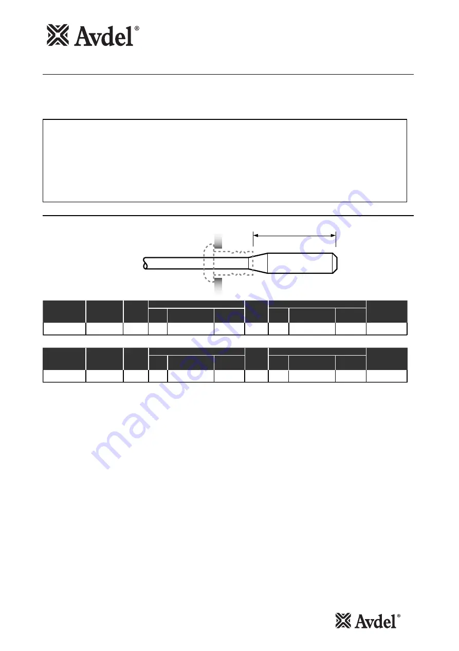
Mandrel Head Types and ‘P’ Length
AVLUG
®
P
1/16"
AVLUG
®
FASTENER
REFERENCE
NUMBER
STANDARD MANDREL- GREEN
1st OVERSIZE MANDREL- YELLOW
'P'
HEAD
MAXIMUM
MANDREL PART
NUMBER
SPRING PART
NUMBER
27-1
0.565
0.381
07155-06702
07154-06802
'P'
HEAD
MAXIMUM
MANDREL PART
NUMBER
0.515
HOLE
SIZE
AS REC
0.335
07154-06602
HOLE
SIZE
+
0.005
1/16"
AVLUG
®
FASTENER
REFERENCE
NUMBER
STANDARD MANDREL- GREEN
1st OVERSIZE MANDREL- YELLOW
'P'
HEAD
MAXIMUM
MANDREL PART
NUMBER
SPRING PART
NUMBER
27-1
1.44
9.68
07155-06702
07154-06802
'P'
HEAD
MAXIMUM
MANDREL PART
NUMBER
1.31
HOLE
SIZE
AS REC
9.02
07154-06602
HOLE
SIZE
+
0.10
Use of Mandrels
Mandrels and mandrel follower springs need to be selected to suit the fastener type and size as well as the size of the hole in the
application. Use of the wrong mandrel could increase the risk of breakage and the wear of the mandrel head. Feeding problems could
occur if the wrong mandrel follower spring is used.
Summary of Contents for 7536
Page 5: ...5 Notes...