


S
E R V I C I N G T H E T O O L
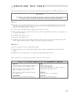
Regular servicing should be carried out and a comprehensive inspection performed annually or every 500000 cycles, whichever is sooner.
I M P O R T A N T
The employer is responsible for ensuring that tool maintenance instructions are given to the appropriate personnel.
The operator should not be involved in maintenance or repair of the tool unless properly trained.
D A I L Y
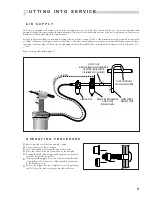
Daily, before use or when first putting the tool into service, pour a few drops of clean, light lubricating oil into the air inlet of the
tool if no lubricator is fitted on air supply. If the tool is in continuous use, the air hose should be disconnected from the main air
supply and the tool lubricated every two to three hours.
Check for air leaks. If damaged, hoses and couplings should be replaced by new items.
If there is no filter on the pressure regulator, bleed the air line to clear it of accumulated dirt or water before connecting air hose to
tool. If a filter is fitted, drain it.
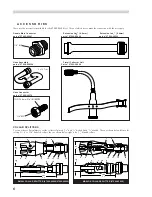
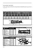
Check that the nose equipment is correct.
Ensure deflector
52
is fitted to the tool.
Check that the stroke of the tool meets the minimum specification (inside front page). It is the distance travelled by the chuck collet
with nose equipment fitted, measured before trigger is pressed and when trigger is fully depressed.
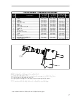
W E E K L Y
Check for oil leaks and air leaks on air supply hose and fittings.
Dismantle and clean the nose assembly, with special attention to the jaws (lubricate with Moly Lithium grease EP 3573 before
refitting).
Lubricate the cam faces and bearing faces on the collar splitters with Moly Lithium grease EP 3753.
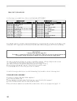
Grease can be ordered as a single item, the part number is shown in the service kit below.
11
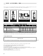
FIRE
FLASH POINT: Above 220
°
C.
Not classified as flammable.
Suitable extinguishing media: CO
2
, Halon or water spray
if applied by an experienced operator.
HANDLING
Use barrier cream or oil resistant gloves
STORAGE
Away from heat and oxidising agent.
FIRST AID
SKIN: As the grease is completely water resistant it is best
removed with an approved emulsifying skin cleaner.
INGESTION: Make the individual drink 30ml Milk of
Magnesia, preferably in a cup of milk.
EYES: Irritant but not harmful. Irrigate with water and
seek medical attention.
ENVIRONMENT
Scrape up for burning or disposal on approved site.
M O L Y L I T H I U M G R E A S E E P 3 7 5 3
S A F E T Y D A T A
■
■
■
■
■
■
■
■
■
Summary of Contents for 07500
Page 17: ...15 15...