

P/N 700514542 B01
About Avaya
Businesses are built on the experiences they provide
and every day millions of those experiences are built
by Avaya (NYSE:AVYA). For over one hundred years,
we’ve enabled organizations around the globe to win—
by creating intelligent communications experiences for
customers and employees. Avaya builds open, converged
and innovative solutions to enhance and simplify
communications and collaboration—in the cloud, on
premise, or a hybrid of both. To grow your business, we’re
committed to innovation, partnership, and a relentless
focus on what’s next. We’re the technology company you
trust to help you deliver Experiences that Matter. Visit us
at
Setting Up this Device
The XT Advanced Camera II can be used as the first
camera on XT5000 Series, XT7000 Series, XT4000
Series and XT Executive 240, or as an additional camera
on XT5000 and XT7000. Please follow the following
instructions to connect and use XT Advanced Camera II.
CAUTION:
Make sure all units are switched off whenever
connecting or disconnecting devices.
Help
IR SELECT
1 2 3
SYSTEM SELECT
DVI OUT
RS-232 IN
RS-232 OUT
1 2 3 4 5 6 7 8 9
DC IN
12V
1 2 3
IR
SELECT
SYSTEM SELECT
DVI OUT
RS-232 IN
RS-232 OUT
1 2 3 4 5 6 7 8 9
DC IN
12V
1 2 3
IR
SELECT
CAUTION: the mains
cable is used as a
disconnecting device,
use therefore an easily
accessible outlet
located near the
device for the power
supply connection.
Never remove the
mains plug while the
device is connected.
On the connector panel of the camera, there is a switch
with three possible positions. Depending on the setting,
it is possible to control the camera using the XT remote
control as described below:
IR ID 1
> Premium camera remote controller
IR ID 2
> Avaya XT remote controller IR ID 97
IR ID 3
> Avaya XT remote controller IR ID 98
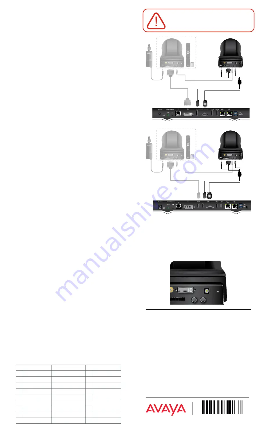
XT5000 Series Codec Unit
XT7000 Series Codec Unit
VISCA Cable
VISCA Cable
SYSTEM SELECT
DVI OUT
RS-232 IN
RS-232 OUT
2 3 4 5 6 7 8 9
1 2 3
IR
SELECT
١
© 2020 Avaya Inc. All Rights Reserved. Avaya and the Avaya logo are trademarks of Avaya Inc. and are regis-
tered in the United States and other countries. All other trademarks identified by ®, TM, or SM are registered
marks, trademarks, and service marks, respectively, of Avaya Inc. 04/20 • 700514542 Avaya XT Advanced II
Camera - Quick Setup Guide
1. Use Advance Camera II as a main
Camera
Step 1
Insert the three connectors to their sockets at the rear of
the camera:
•
The DVI connector to the DVI socket.
•
The 8-pin connector to the Camera Ctrl IN socket.
•
The power connector to the DC IN 12V socket.
Step 2
Attach the two connectors to the camera sockets at
the rear of the XT Series endpoint (XT4000, XT5000,
XT7000 or XT Executive 240):
•
The HDMI connector to the vertical socket
•
The connector for power and serial control to the
horizontal socket.
Step 3
Check that HD1 camera is enabled in the menu
Configure
> Advanced > I/O connections > Cameras > HD1
2. Use Advanced Camera II as an
additional camera
NOTES:
Cables and power supply unit needed to connect
the camera as additional camera are provided with the
Optional Cameras Cable kit (#700512192).
Step 1
Connect the Advanced Camera II to the XT5000 Codec
Unit’s DVI input (instead of connecting a PC), or to the
second HDMI input of XT7100.
Step 2
Connect the VISCA control cross cable between the
Camera Ctrl Out of the first camera with Camera Ctrl In
of the second camera.
Step 3
Connect the power supply of the optional camera to the
mains, then switch on the Codec Unit.
Step 4
Enable the camera input in its related menu “
Configure >
Advanced > I/O Connection > Cameras > DVI > Enable
= Yes
”
or
“
Configure > Advanced > I/O Connection
> Cameras > HD2 > Enable = Yes
”. In the same menu
select “
Control Camera = Yes
” and verify that the “
Driver
= XT Series Advanced Camera II
”. For any further
configuration details, see the XT Administrator guide.
To control the optional camera from your XT Series
endpoint, you need to connect a VISCA cable between
the two cascaded cameras.
VISCA Cable
VISCA Control is a standard protocol to control PTZ
Cameras. You can buy a VISCA cross cable from a third
party or make your own cable if you’re planning to
position the optional camera far away from the Codec
Unit. The VISCA cross cable is an 8-pin mini-DIN male to
mini-DIN male cable with the following Pinout diagram
VISCA IN
VISCA OUT
1
One
O———————O
2
Two
2
Two
O———————O
1
One
3
Three
O———————O
5
Five
4
Four
O———————O
4
Four
5
Five
O———————O
3
Three
6
Six
O———————O
6
Six
7
Seven
O———————O
7
Seven
8
Eight
O———————O
8
Eight
SHIELD
O———————O
SHIELD