Avaya P133F2 Quick Start Manual Download Page 4

Power up

Avaya P130

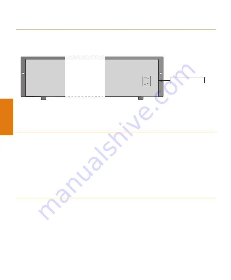
1.  Insert the power cord into the power connector (BUPS or Power Supply) on the rear of the

unit.

2.  Insert the other end of the power cord into the electricity supply.

The unit powers up and performs a self test procedure. The OPR AND PWR LEDs are
on after the self-test procedure is completed successfully.

Connect the cables

Connect PCs, servers, routers, workstations, and hubs

1.

Connect the Ethernet connection cable (not supplied) to a 10/100 Mbps port on the front
panel of the P130. 

You should use standard RJ-45 connections. You must use CAT-5 cable for 100 Mbps
operation.

2.

Connect the other end of the cable to the Ethernet port of the PC, server, router, worksta-
tion, switch or hub.

Use a cross cable when connecting the P130 to a switch or hub.

3.

Check that the appropriate link (LNK) LEDs light up.

Connect the console cable

1.

Configure the serial port settings of the PC or terminal as follows: Baud Rate – 9600, Parity
– no, Data bits – 8, Stop bits – 1, Flow control –  no.

2.

Connect the supplied special RJ-45 connector to the port marked “Console” on the front
panel of the P130.

3.

Connect the other end of the cable to a terminal or PC with terminal emulation software
installed.

3

Power Supply

Connector

AC connector

Summary of Contents for P133F2

Page 1: ...Avaya P133F2 Quick Start Guide Unpack Rack mount optional Connect the cables Configure Run Web based Manager optional Power up 1 2 3 4 5 6...

Page 2: ...CD see detail below Avaya Warranty and License Agreement Avaya P130 Documentation and Utilities CD The CD contains the latest Technical Documentation for the Avaya P130 Workgroup switches and files f...

Page 3: ...ING Disconnect all cables from the unit before proceeding with the rack installation 13 14 15 16 17 1 LAG 2 3 4 5 CONSOLE 21 18 19 20 23 22 24 9 6 LAG 7 8 11 10 LAG 12 P133F2 51 FDX 15 52 COL LNK Tx R...

Page 4: ...use standard RJ 45 connections You must use CAT 5 cable for 100 Mbps operation 2 Connect the other end of the cable to the Ethernet port of the PC server router worksta tion switch or hub Use a cross...

Page 5: ...indicates port speed of 10 Mbps OPR Shows CPU boot and BIT status PWR Shows power ON OFF Avaya P133F2 LEDs Basic configuration To connect a PC terminal or VT 100 terminal to the Avaya P130 1 If you ar...

Page 6: ...rameters which you need to enter are shown in as follows vlan 1 Type set interface inband vlan ip_address netmask replacing vlan ip_address and netmask with the VLAN IP address and net mask of the sta...

Page 7: ...Port Priority 0 Spanning Tree Cost 10 100BaseTX ports 100 100BaseFX ports 20 1000BaseF ports 4 Spanning Tree Port Priority 80 Hex 5 Default Switch Parameters Configuration Parameter Default Setting P1...

Page 8: ...he Documentation and Utilities CD Refer to the Release Notes for the exact version of the Java plug in Running the Embedded Manager Assign an IP address to the P130 before starting this procedure 1 Op...

Page 9: ...our PC 2 Insert the Avaya P130 Documentation and Utilities CD in the CD drive 3 Open Windows Explorer 4 Open the embweb aux files folder on the CD 5 Double click on the plugin_a_b_c exe file a b and c...

Page 10: ...Documentation and Online Help Refer to the Avaya P130 Documentation and Utilities CD for full instructions...

Page 11: ...Notes...

Page 12: ...13839 Iceland 0800 8125 Country Local Dial In Number Ireland 353 160 58 479 Israel 1 800 93 00 900 Italy 39 02 7541 9636 Jordan 31 70 414 8045 Kazakhstan 31 70 414 8020 Kenya 31 70 414 8049 Kuwait 31...

Reviews: