background image

SpectraLink Corporation 

LinkPlus Interface Guide 

Avaya DEFINITY Communications System 

Part Number: 72-0171-01-B.doc 

Page 3 

1. About 

LinkPlus 

SpectraLink is the market leader in multi-cellular wireless telephone systems for the 
workplace. We manufacture a range of products to suit any size installation. All 
SpectraLink products use our LinkPlus digital integration technology to integrate with 
various digital switch platforms.  Using LinkPlus technology, Wireless Telephones 
emulate digital telephone sets to deliver advanced capabilities such as multiple line 
appearances and LCD display features. This document explains the programming or 
administration required to use the host digital switch with the following SpectraLink 
products: 

Link Wireless Telephone System (Link WTS)– Link 3000 MCU 

The Link WTS 3000 supports up to 3,200 Wireless Telephones and up to 1,000 Base 
Stations.  Up to 25 shelves can be interconnected for maximum system capacity. 

Link Wireless Telephone System (Link WTS) – Link 150 MCU 

Designed for smaller installations supporting up to 64 Wireless Telephones and up to 16 
Base Stations. Up to four MCU controllers can be interconnected for maximum system 
capacity. 

NetLink Telephony Gateway 

The NetLink Telephony Gateway is a wireless LAN-based telephony product that 
provides high quality packetized voice communications using the Internet Protocol (IP). 

1.1 Contacting 

SpectraLink 

SpectraLink wants you to have a successful installation.  If you have questions please 
contact our 

Customer Support Hotline at  (800) 775-5330.

  The Hotline is open 

Monday through Friday, 6:00 AM to 6:00 PM Mountain Time. 

1.2  Icons and Conventions 

This manual uses the following icons and conventions. 


Caution! Follow these instructions carefully to avoid danger. 


Note these instructions carefully. 

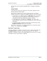
NORM 

This typeface indicates a key, label, or button on SpectraLink hardware. 

Summary of Contents for LinkPlus

Page 1: ...LinkPlus Interface Guide Avaya DEFINITY Communications System Link Wireless Telephone System NetLink Wireless Telephone Part Number 72 0171 01 Issue B ...

Page 2: ...ited to statements regarding capacity response time performance suitability for use or performance of products described herein shall be deemed to be a warranty by SpectraLink for any purpose or give rise to any liability of SpectraLink whatsoever In no event shall SpectraLink be liable for any incidental indirect special or consequential damages whatsoever including but not limited to lost profit...

Page 3: ...Wireless Telephones and up to 1 000 Base Stations Up to 25 shelves can be interconnected for maximum system capacity Link Wireless Telephone System Link WTS Link 150 MCU Designed for smaller installations supporting up to 64 Wireless Telephones and up to 16 Base Stations Up to four MCU controllers can be interconnected for maximum system capacity NetLink Telephony Gateway The NetLink Telephony Gat...

Page 4: ...em features ringing options etc to be programmed for the Wireless Telephones One of these scenarios concerning how the Wireless Telephones are programmed should apply to this site All Wireless Telephones are programmed alike All Wireless Telephones will be programmed exactly the same Depending on the capabilities of the switch the system administrator can often program one Wireless Telephone and u...

Page 5: ...if any should be programmed on the Wireless Telephones These assignments may emulate assignments on the user s wired set It will help to identify a wired set that is programmed exactly or close to the way the Wireless Telephones should be programmed This set can be duplicated to copy station parameters to the Wireless Telephones 2 2 Assign Extension Numbers The wire contractor should inform the sy...

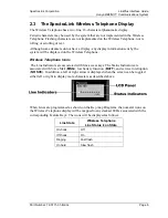
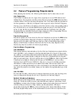
Page 6: ...ll be displayed on the Wireless Telephone Wireless Telephone Icons The Line Indicators are associated with line access keys The Status Indicators are associated with Voice Mail MSG low battery function BATT and service interruption NO SVC In addition a left or right arrow is displayed when the screen can be toggled either left or right to display more characters as described above When Lines are p...

Page 7: ...rogramming Function Menu Programming Link 3000 MCU Note that the function menu defaults set for the Wireless Telephones associated with the Link 3000 MCU can be changed via the SpectraLink Operator s Console If the system uses softkeys to minimize unwanted interaction between system display and the Wireless Telephone function menu display configure the Wireless Telephone menu to include a delay of...

Page 8: ...reless Telephone is activated with the message indication of the deskset The voice mail feature on the deskset must be assigned to the feature key as shown in the Key map Diagrams Do not assign any other feature to this key since the associated LED is directly mapped to the message waiting icon on the Wireless Telephone This LED assignment must be used in order to support the message waiting icon ...

Page 9: ... Telephone System with a DEFINITY Communications System The procedures assume The DEFINITY system is installed and operational in an approved configuration See the Telephone Switch Interface Matrix document for tested configurations A trained DEFINITY technician will be on site with the Installer to program the system The Link WTS or NetLink Telephony Gateway is installed and the Wireless Telephon...

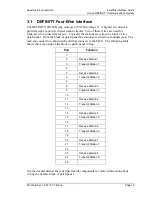
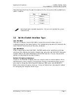
Page 10: ...red to a modular jack The jack can connect to a short patch cord that connects to the MCU The following table shows the Avaya side of the block or patch panel wiring Pair Function 1 2 Receive Station 1 3 Transmit Station 1 4 5 Receive Station 2 6 Transmit Station 2 7 8 Receive Station 3 9 Transmit Station 3 10 11 Receive Station 4 12 Transmit Station 4 13 14 Receive Station 5 15 Transmit Station 5...

Page 11: ...es are detailed in the Link 150 MCU Installation and Operation document Link 3000 MCU When configuring the Link 3000 MCU the PBX interfaces are available as sub menu selections when defining the Interface Module type using the Link 3000 MCU Operator s Console Refer to the Link 3000 Master Control Unit Operator Console document for details on configuring the Interface Modules NetLink Telephony Gate...

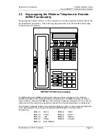
Page 12: ... 1 FCN 2 FCN 3 FCN 4 Menu PREV NEXT FCN 5 FCN 6 FCN 7 FCN 8 EXIT DEFINITY 8410D Key mapping The FCN number and LINE number labels represent the key sequence on the Wireless Telephone mapped to the corresponding key on the desk set The FCN sequence is used to map to softkeys Pressing the FCN key on the Wireless Telephone followed by the key and the number key is the sequence equivalent to pressing ...

Page 13: ...late Wireless Telephone If there is no 8410D available find a station that has similar settings and use the display or print station command to check the settings so they can be manually duplicated using an add station command for the template Wireless Telephone Station Features for Wireless Telephone Station features on Page 1 of the station form can be assigned or copied as determined in the pre...

Page 14: ...he Wireless Telephone to correspond to the first three appearances on the wired station Assign buttons 4 5 as call appearances call appr This must be done because DEFINITY requires at least two call appearances of the extension on each station To make the Wireless Telephone ring when the wired station rings change Bridged Call Alerting to Yes on the wired station If the Wireless Telephone is not a...

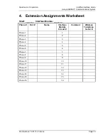
Page 15: ...5 4 Extension Assignments Worksheet Shelf _______ Interface Module _______ Phone Ext Name Interface Module Circuit Comment Wireless Telephone Serial Phone 1 1 Phone 2 2 Phone 3 3 Phone 4 4 Phone 5 5 Phone 6 6 Phone 7 7 Phone 8 8 Phone 9 9 Phone 10 10 Phone 11 11 Phone 12 12 Phone 13 13 Phone 14 14 Phone 15 15 Phone 16 16 ...

Reviews: