background image

About the Handset 

Programming & Using the MDW 9040 Pocket Phone 

5

MDW 9040 Wireless Pocket Phone Installation and Use, 

503-801-190

Issue 2, February 2001

47

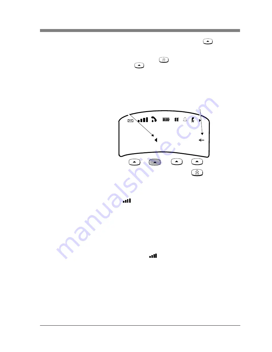
Located under the display are four Column buttons, labeled 


(in Menu 

Mode, these four buttons are called Softkeys). Each Column button affects one of the 
four columns or programmable/intercom/drop buttons directly above it.

Once you have moved the Select-Row (

) button to the row you wish to access, 

press the Column button (

) to select the line or programmable/intercom/drop 

button in that row.

For example, if you press the second Column button from the left (shaded in 

Figure 17

 below), you select Line 2, as indicated by the triangle (for PARTNER) next 

to 2 in the figure below.

Figure 17. Using the Select-Row and Column Buttons Together

Signal Strength and 
Range Indicators

Signal Strength is indicated by the number of bars in the Radio Frequency (RF) 
Signal Level 
icon (

). Four bars indicate optimal signal level, while one bar or no 

bars indicate poor signal level.

Note:

The antenna must be either fully retracted (for short range) or fully 
extended (for maximum range) to use the Pocket Phone.

Approaching Out of Range: The handset provides an audible and a visual signal to 
alert you when the handset is near the end of the range of the radio module. 
Depending on how far away the handset is from the radio module, the signals 
function as follows:

During a call, the handset emits 2 beeps and/or turns on the vibrator for a short 
period of time and flashes the 

 icon continuously.

5

1

A

6

2

B

7

3

C

8

4

D

Select-Row arrow

Column Selection pointer

7/18 Tues

Summary of Contents for IP Office TransTalk MDW 9040

Page 1: ... RPFRGH VVXH HEUXDU 7UDQV7DON LJLWDO LUHOHVV 6 VWHP 0 LUHOHVV 3RFNHW 3KRQH QVWDOODWLRQ DQG 8VH ...

Page 2: ... 2001 by Avaya Communication All rights reserved For trademark regulatory compliance and related legal information see the Copyright and Legal Notices section ...

Page 3: ...elecommunications services You are responsible for the security of your system There may be a risk of toll fraud associated with your telecommunications system You are also responsible for programming and configuring your equipment to prevent unauthorized use Your system administrator should read all documents provided with this product to fully understand the features that can introduce the risk ...

Page 4: ...Wireless Pocket Phone with a PARTNER MERLIN MERLIN LEGEND or MERLIN MAGIX System Consultation charges may apply In the continental U S call 1 800 225 7585 if you need assistance when installing the Dual Radio Module for an MDW 9040 Wireless Pocket Phone with a DEFINITY System or contact the Avaya Customer Care Center at 1 800 242 2121 Consultation charges may apply Outside the continental U S cont...

Page 5: ...one and Dual Zone Configuration 13 Installation Procedures for Dual Radio Modules 14 Wall Mounting the Dual Radio Module 14 Installing a Dual Radio Module 15 Installing Multiple Radio Modules for Single Zone Operation 15 Installing Multiple Radio Modules in a Dual Zone Configuration 17 Dual Zone Administration 19 Administration for PARTNER 19 Administration for MERLIN 410 and 820 19 Administration...

Page 6: ...Phone 43 Important Safety Instructions 43 About the Handset 43 Handset Features 44 The Handset Display 45 Setting or Changing Handset Settings 50 Features and Options 52 A Flowchart for the Configuration Options and Test Mode Display Screens 59 Test Modes 60 Using Handset Features 66 Waking Up the Phone 66 Placing a Call 66 Answering a Call 66 Manually Selecting a Line or Programmed Button 67 Pres...

Page 7: ... of Liability 92 Repair Information 92 In Warranty Repairs 92 Post Warranty Repairs 92 Appendix B Regulatory Information 93 FCC Part 15 Rules 93 IC RSS 210 Compliance 93 Hearing Aid Compatibility 93 Appendix C Specifications 95 Appendix D Ordering Replacement and Optional Parts 97 Appendix E Wall Mounting Templates 99 Battery Charger Wall Mounting Template 99 Multiple Dual Radio Modules Spacing Wa...

Page 8: ...Contents MDW 9040 Wireless Pocket Phone Installation and Use 503 801 190 viii Issue 2 February 2001 ...

Page 9: ...ons systems including PARTNER MERLIN MERLIN LEGEND MERLIN MAGIX and DEFINITY switches The MDW 9040 is different from its predecessors in several ways The base station to which the handset is linked is called a Dual Radio Module because each module can support two handsets simultaneously Synchronization of multiple Dual Radio Modules and handsets is accomplished without a carrier The radio module i...

Page 10: ... the privacy and security of your voice conversation The phone uses continuously changing radio frequencies and digital encoding techniques to make it impossible for eavesdropping to occur through the use of commercially available analog radio scanners Where Can You Use Your Pocket Phone The MDW 9040 Pocket Phone can be used in most typical office buildings warehouses factories malls and even outd...

Page 11: ...e following Figure 1 Handset Packaging Components AB 23 4 6 5 MSG 212 555 1212 ON 78 CD 1 Feat P Conf GHI PQRS OPER Trans Hold Redial 1 2 4 JKL ABC 3DEF 5 MNO 6 TUV 8 0 WXYZ 9 7 Menu Handset SPAREHANDSET REFRESH Battery Charger and Wall Mounting Kit Battery Pack 8 inch 0 5 m Lanyard 11 foot 3 4 m Power Cord AC Adapter for Battery Charger Standard Battery Pack Carrying Clip 9040 2 Wall Spacers 2 Ph...

Page 12: ... either an additional second standard battery pack or an extended battery pack For more information about battery packs see Inserting a Battery Pack into the Spare Battery Compartment in Chapter 2 Optional Supra Mobility headsets can be attached to a quick disconnect adapter cord which you can insert into the connector on the bottom of the handset to allow hands free conversation specifically desi...

Page 13: ...ts housing becomes cracked or otherwise damaged To clean your phone wipe the outside housing with a soft dust free cloth If absolutely necessary you may use a cloth slightly dampened with a mild soap and water solution Dry quickly with a soft cloth CAUTION Your phone contains sensitive electronic parts Never submerge it in any kind of liquid and never use liquid or aerosol cleaners detergents alco...

Page 14: ...shielded from RF energy RF energy from wireless telephones however may affect some electronic equipment Although the TransTalk wireless telephone is compatible with inductively coupled hearing aids a physician or hearing aid manufacturer should be consulted to determine if a hearing aid is adequately shielded from external RF energy The operation of inadequately shielded medical devices may be adv...

Page 15: ...ety Instructions for Installation Personnel Install the product to meet all environmental and electrical requirements listed in Appendix C Specifications All wiring that connects to this equipment and becomes part of the building wiring must be a minimum of CLASS 2 or UL Underwriters Laboratories Listed Communications cable Do not install telephone wiring during a lightning storm Do not install te...

Page 16: ...ns system to which the MDW 9040 is connected Make sure you have mapped the buttons to the correct system See Chapter 6 MDW 9040 Pocket Phone Compatibility for more information 4 Choosing features and options A menu of features and options is available to configure your handset See About the Handset in Chapter 5 About the Dual Radio Module Each radio module can communicate with up to two handsets H...

Page 17: ...the radio module to the station port interface Before you use the MDW 9040 Pocket Phone you must register each of the two handsets with the associated radio module Note The power for the radio modules is provided by the switch when the Station Line Cord is connected from the switch to either of the Line Jacks An optional auxiliary power supply can be provided in which case the line cord connects i...

Page 18: ... radio module can be the control radio module All other radio modules must be expansion amber LED radio modules When this LED is It indicates The Power LED Top STEADY GREEN The radio module is receiving power from the switch or auxiliary power supply NO LIGHT The radio module is not receiving power is connected to the wrong switch or has failed FLASHING The radio module is in Registration or Wirel...

Page 19: ...ted to these systems will have a maximum loop length of 3 000 feet 915 m The following auxiliary power supplies are preferred The 1151A1 Power Supply PEC 2404 010A Comcode 108212952 or the 1151A2 Power Supply with Battery Holdover PEC 2404 012A Comcode 108212960 Note If you are using an auxiliary power supply the MDW 9040 Pocket Phone has a built in testing feature that you can use before final in...

Page 20: ...ed concrete General Positioning Rules Failure to observe the following rules regarding location and use will result in poor performance of your MDW 9040 Pocket Phone The Synchronization cable connecting two radio modules is 20 inches 50 cm long When positioning radio modules they must be installed with a minimum separation that is provided by the base wings of the radio module 5 1 4 A template for...

Page 21: ...e to the communications system switch control unit IROBs and if required by distance limitations an auxiliary power supply must be used for out of building installations Note You should perform the tests described in Using Wireless Test Mode in Chapter 5 to determine the optimal placement of the radio module Single Zone and Dual Zone Configuration Multiple radio module units can be installed and c...

Page 22: ...ient to unpack the radio module and handset in the switch room power up the radio module and then register the handset prior to installing the radio module For this procedure refer to the introductory information and figures for the radio module in this section and then follow the registration procedures outlined in Chapter 4 Registering the Pocket Phone to a Dual Radio Module or see A Quick Refer...

Page 23: ...r the first handset to be connected to the radio module connect a 14 foot 4 2 m Station Line Cord provided to Line 1 on the radio module and then connect the other end of the cord to a station port at the main communication system If a second handset is to be connected to the radio module connect another Station Line Cord to Line 2 on the radio module and then connect the other end of that cord to...

Page 24: ...e Steady Amber Note Radio modules can be installed in a single zone or dual zone configuration with up to the same number of handsets that is 9 radio modules 18 handsets per zone for key systems such as PARTNER or MERLIN or MERLIN MAGIX and up to 15 radio modules 30 handsets for PBX systems such as MERLIN LEGEND or MERLIN MAGIX in PBX mode and DEFINITY The following is a diagram showing three radi...

Page 25: ...t be connected to an associated switch the radio module can be temporarily connected to an auxiliary power supply that can provide electrical power 3 Verify that the radio module has power and that the status LED information is correct See Dual Radio Module Light Indications on page 10 4 Repeat Steps 1 and 2 for each radio module and handset combination in this configuration 5 To daisy chain two o...

Page 26: ... Regarding Zone Overlaps Separate the radio modules so that you have continual coverage yet no overlap recommended or minimal overlap between zones If there is an overlap condition poor voice quality could occur and the Range icon may begin flashing in the handset display If this occurs move the radio module further from the original installation position Figure 7 Ideal Dual Zone Installation Dual...

Page 27: ...em from the sections that follow and perform the administration tasks provided Note Features lines and ringing options administered for any of the communications systems should be administered identically for both zones station port 1 and station port 2 so that your pocket phone operates the same way in either zone Administration for PARTNER For PARTNER Communications Systems you must administer 2...

Page 28: ...5 0 For DEFINITY Communications Systems prior to Release 5 0 you must administer 2 station ports 2 extensions one for each radio module Each station port must be administered with 3 call appearances of its own and 3 bridged appearances of the other station extension number Administration for DEFINITY After Release 5 0 For DEFINITY Communications Systems after Release 5 0 you must administer 2 stat...

Page 29: ...1 Coverage Path 2 Hunt to Station Personalized Ringing Pattern Message Lamp Ext Mute Button Enabled n 1 30016 30016 TransTalk Dual Zone 1 TN 1 Display Language english MM Complex Data Ext STATION Page 2 of 4 SPE B Auto Select Any Idle Appearance n add station next FEATURE OPTIONS LWC Reception spe AUDIX Name n Messaging Server Name n Per Station CPN Send Calling Number Multimedia Early Answer n Au...

Page 30: ...r prog 10 abr spchar Char p 11 abr spchar Char m 12 abr spchar Char w STATION Page 4 of 4 SPE B add station next lwc store Note All Softkey button assignments should be initially removed when administering an MDW 9040 Dual Zone terminal The desired Softkey features can then be properly programmed on the Dual Zone Pocket Phone programmable buttons 1 7 Button 8 is a firmware programmed hard Scroll b...

Page 31: ...ct Last Used Appearance n Page 3 of 4 SPE B add station next Room Jack Cable Floor Building SITE DATA 1 2 3 4 5 ABBREVIATED DIALING BUTTON ASSIGNMENTS List1 List2 List3 STATION Headset Speaker Mounting Cord Length Set Color n n d 0 A brdg appr Btn 1 Ext 30016 B brdg appr Btn 2 Ext 30016 C brdg appr Btn 3 Ext 30016 1 2 6 3 7 4 8 5 9 6 10 7 SOFTKEY BUTTON ASSIGNMENTS 1 2 lwc cancel 3 auto cback 4 ti...

Page 32: ...roperly grounded electrical outlet that is not controlled by an on off switch If your communications system uses an uninterruptible power supply such as a backup generator you may want to connect the battery charger to that power supply Do not locate the battery charger where it will be exposed to direct sunlight or water WARNING The rechargeable battery pack may contain elements that are harmful ...

Page 33: ...d by a wooden stud if unavailable use toggle bolts instead of the supplied wood screws Hold the template straight use a level if needed 3 Mark the locations for the two wall mounting screws and then remove the template from the wall Lightly tap a nail into the wall to start the holes 4 Place the screw through the wall spacers so that the screw head nests in the indentation on the spacer Start the ...

Page 34: ...d that is with the back of the battery pack against the back of the spare battery compartment Do not force the battery pack down The battery pack should slide easily into the slot Correct positioning of the battery pack in the charger is important to ensure proper charging The bottom end of either battery pack also has two small round holes that must align with two guide pins on the bottom of the ...

Page 35: ...attery Pack Into Spare Battery Compartment Removing a Battery Pack from the Spare Battery Compartment To remove a battery pack from the spare battery compartment of the charger lift the battery pack up and out Handset Cradle SPARE LED Vertical Guide Rail Spare Battery Compartment Vertical Guide Rail Spare Battery Pack Guide Pin Battery Charger Contacts Spare Battery Pack ...

Page 36: ...rt the charged battery pack in the handset The following explains how to install the handset battery pack To insert the battery pack into the handset 1 Insert the two small rectangular tabs located along the bottom back edge of the handset into the two rectangular holes along the bottom front edge of the battery pack 2 Press the battery pack downward until it clicks into place Note The battery pac...

Page 37: ...ositioning of the handset in the charger is important to ensure proper charging 1 Position the handset with either battery pack attached so that the two small round holes in the bottom of the handset fit over the two guide pins on the bottom of the handset cradle 2 Rock the handset back into the cradle until it is firmly seated with the back of the handset battery pack against the back of the hand...

Page 38: ...nto the Battery Charger Removing the Handset from the Handset Cradle To remove the handset from the handset cradle lift it out SPARE HANDSET REFRESH OPER 0 Feat P Conf GHI PQRS Trans Hold Redial 1 2 4 JKL ABC 3DEF 5 MNO 6 TUV 8 WXYZ 9 7 Menu SPARE HANDSET REFRESH Feat P Conf GHI PQRS OPER Trans Hold Redial 1 2 4 JKL ABC 3DEF 5 MNO 6 TUV 8 0 WXYZ 9 7 Menu HANDSET LED Guide Pins 9040 9040 ...

Page 39: ...ect which reduces a battery s capacity occurs over time when you repeatedly recharge a battery before it is fully discharged The handset cradle charges a battery pack in the handset The REFRESH button when pressed refreshes the handset battery pack in the handset cradle by fully discharging the battery pack before recharging it The REFRESH and the HANDSET LEDs go on when the REFRESH button is pres...

Page 40: ...tton Battery charger LED shows If it is the SPARE LED the battery pack in the spare battery compartment If it is the HANDSET LED the battery pack in the handset If it is the REFRESH LED the Refresh button was pressed and the handset battery pack Steady orange Is charging Is charging N A Steady green Is fully charged Is fully charged N A Flashing red See Note below Has one of the following problems...

Page 41: ...s between the handset and the spare battery compartment at least once a week so that each battery pack is automatically refreshed Alternate the battery packs even if the handset battery never flashes the Battery icon in the handset display to indicate a low battery condition The average battery life for both the standard and the extended battery packs is approximately one year assuming that the ba...

Page 42: ...3 Using the Battery Charger The Battery Charger MDW 9040 Wireless Pocket Phone Installation and Use 503 801 190 34 Issue 2 February 2001 ...

Page 43: ...ocket Phone There you will find a drawing of the handset with a description of its features and procedures for configuring and using your telephone as well as directions for performing a Local and a Wireless Test of the handset Registering a Handset To register your handset with the radio module to which it will be connected in a single zone configuration or the first zone of a dual configuration ...

Page 44: ...ted radio module makes checks regarding the handset registration request If there are no unexpected conditions the associated base module and handset communicate using special link up signaling The handset displays the following screen when registration is completed When selecting Registration in Step 5 this screen displays if the handset was previously registered Note Repeat these procedures for ...

Page 45: ... zone operation The following occurs The second radio module makes checks regarding the handset registration request If there are no unexpected conditions the associated base module and handset communicate using special link up signaling The handset displays a Registration Completed message to the user The LEDs on the radio module have the following meaning Flashing Power LED Handset is in Registr...

Page 46: ...any changes at this time press the Softkey below Back To exit Menu Mode press the Menu button 4 Once all handsets have been registered proceed to the instructions in Mapping to the Correct Communications System on page 40 Removing Registration Between a Handset and a Dual Radio Module To unregister a handset and a radio module 1 Follow Steps 1 through 5 of the registration procedures 2 At the Regi...

Page 47: ...e corresponding to the Line 1 or 2 to which the handset will be registered The corresponding radio module LED will flash to indicate that the radio module is ready for handset registration STEP 5 Press the Softkey below Reg on the handset display to complete the registration process The handset display should indicate a successful completion and the radio module LED should stop flashing REGISTRATI...

Page 48: ...ed and when the radio module is connected to the switch the associated default button mapping will flash The table below lists the default switch interfaces for each radio module type If your communication system is not the default switch listed in the table above you must set the correct Button Mapping Use the following procedures to verify that your handset is mapped to the correct communication...

Page 49: ...start over at Step 1 Filling Out the Handset Label Once you have checked to make sure that the MDW 9040 is mapped to the correct communications system fill out the handset label on the back of the handset The MDW 9040 display shows the status of up to 12 lines or programmable intercom drop buttons Since the MDW 9040 is compatible with several different communications systems diagrams of the button...

Page 50: ...ocate the section in Chapter 6 that describes the button mapping for your communications system then copy the mapping to the label for ease of reference Other Handset Configuration Options Before using your handset and its display you may also wish to do the following Select the Display 1 or 2 lines For more information about selecting the display length see Chapter 5 Programming Using the MDW 904...

Page 51: ...Chapter 2 About the Handset The MDW 9040 Wireless Pocket Phone supports normal operation of all of the features of the switch as far as is practical within the limitations of its reduced size and power and the nature of wireless operation There are very few differences in operation between the wireless MDW 9040 Pocket Phone and a wired deskset This chapter describes the handset and how to use it I...

Page 52: ...ton Also used to wake up the phone 7 Dial Pad The usual 12 button dial pad for placing calls or accessing features 8 Headset Connector Plug in the headset adapter to use the headset 9 Hold Press to put a call on hold 10 Trans Transfer Press to transfer a call to another extension 11 Conf Conference Press to conference in add another person to your call 12 Feat P Feature Program Press to access swi...

Page 53: ...ht Figure 16 The Top Row of the Display Showing Handset Status Icons 1 A 2 B 3 C 4 D 7 18 Tues 03 27p 00 00 1 The Message icon lights when you have a message 2 The Radio Frequency RF Signal Level icon is divided into four bars to show the radio frequency signal strength 3 The Handset Off Hook Status icon lights when the handset or the headset is off hook on 4 The Battery Charge Level icon is divid...

Page 54: ... Line Status Indicators in the next section See Chapter 6 MDW 9040 Pocket Phone Compatibility for more information about Button Mapping Line Status Indicators There are up to 12 status indicators A through D 1 through 8 see Figure 15 Each one corresponds to a specific outside or intercom line recall and or drop button and programmable buttons The function of these status indicators varies dependin...

Page 55: ... to 2 in the figure below Figure 17 Using the Select Row and Column Buttons Together Signal Strength and Range Indicators Signal Strength is indicated by the number of bars in the Radio Frequency RF Signal Level icon Four bars indicate optimal signal level while one bar or no bars indicate poor signal level Note The antenna must be either fully retracted for short range or fully extended for maxim...

Page 56: ...settings see Setting or Changing Handset Settings on page 50 Low Battery Indicator The Battery Charge Level is indicated by the number of cells displayed on the Battery Charge Level icon If all four cells are filled in the battery is fully charged If two or less cells are displayed it is time to recharge the battery The standard battery pack has approximately three hours of continuous talk time af...

Page 57: ...a chirping sound and the display shows the current volume level Figure 19 Ringer Volume Level Display To raise or lower the volume of the Handset Receiver or the Earpiece While the MDW 9040 is off hook press the press the or the v button Each time you press the or v button the handset audio dial tone level changes and the display shows the current volume level There are four ringer settings Figure...

Page 58: ...Clicks as you press keys on the telephone dial pad From the Test Mode menu Enter Local Test Mode which enables you to test the alerter vibrator and display Enter Wireless Test Mode which enables you to test sound clarity signal strength and voice quality Selecting a Menu Item The Selection control buttons are used to identify fields within three rows the 3rd 4th and 5th rows on your display After ...

Page 59: ...for Select Responding to the Last Line on the Screen On the bottom row of the screen you may see Sel More or Exit Back such as in the following example These options indicate Sel ect you can select the currently highlighted option such as Ringer or Vibrator by pressing the Softkey below Sel More there are more options than shown on the current screen To see the next screen of options press the Sof...

Page 60: ...lect Row button to move the arrow to Configuration 3 Press the Softkey below Sel The initial Configure Menu screen displays Registering the Handset to the Dual Radio Module The Registration feature under the Configure Menu allows you to register the handset with its appropriate radio module For detailed instructions on registering the handset with the appropriate radio module s see the information...

Page 61: ...ngth of a Display message 1 From the initial Configure Menu screen press the Softkey below More The additional Configure Menu feature displays 2 With the Select Row arrow to the right of Display press the Softkey below Sel The Display Menu screen displays Note The currently active option if there is one flashes 3 Press the Select Row button to move the arrow to the display length you want and pres...

Page 62: ...of alerter you want to hear on your phone Select either the Ringer or the Vibrator option or both to alert you when there is an incoming call The Ringer is an audible signal to notify you of an incoming call If a call comes in while the phone is idle the handset rings If you are already on a call the handset chirps softly You can adjust the volume of the alerter by pressing the button or the v but...

Page 63: ... you have moved the Select Row arrow to the appropriate option press the Softkey below Sel Enabling or Disabling the Vibrator To enable or disable the Vibrator option 1 From the initial Options Menu screen press the Select Row button to move the arrow to Vibrator 2 Press the Softkey below Sel The Vibrator Control screen displays Note The currently active option if any flashes indicated by 3 Press ...

Page 64: ...ns Menu screen press the Softkey below More Additional Options Menu options display 2 With the Select Row arrow to the right of Backlighting press the Softkey below Sel The Backlighting Control screen displays Note The currently active option if any flashes indicated by 3 Press the Select Row button to move the arrow to the On or Off option 4 When you have moved the Select Row arrow to the appropr...

Page 65: ...nnect to before turning on the handset The Line Pre Select option can be turned ON or turned OFF Note When Line Pre Select is enabled you do not have to use it however you cannot use it unless it is enabled To enable Line Pre Select 1 From the initial Options Menu screen press the Softkey below More Additional Options Menu options display 2 Press the Select Row button to move the arrow to Pre Sele...

Page 66: ...al Options Menu option displays 2 With the Select Row arrow to the right of Key Clicks press the Softkey below Sel The Key Clicks Control screen displays Note The currently active option if any flashes indicated by 3 Press the Select Row button to move the arrow to the On or Off option 4 When you have moved the Select Row arrow to the appropriate option press the Softkey below Sel 5 If you selecte...

Page 67: ...ack Press the Softkey below More for other options OPTIONS MENU Backlighting Sel More Back Pre Select Press the Softkey below More for other options to select the Test Mode Menu TEST MODE Local Sel Back Wireless Test For Registration choose Zone 1 or Zone 2 For Button Map choose Partner or Merlin Partner Merlin or Merlin 410 820 or Merlin Magix or Definity For Msg Length choose 1 line or 2 lines O...

Page 68: ...ted when pressing all key pad buttons Is the display operational To use Local Test Mode 1 Make sure the handset is turned off 2 Press The initial Menu screen displays 3 Press the Select Row button to move the arrow to Test Mode 4 Press the Softkey below Sel The initial Test Mode Menu screen displays 5 With the Select Row arrow to the right of Local press the Softkey below Sel The handset rings for...

Page 69: ...erform the tests all you need is an electrical outlet for the radio module a 14 foot 4 2 m Station Line Cord provided with an auxiliary power supply and a charged battery pack in the handset You can perform the tests multiple times and in any order you can exit at any time by pressing Note Ignore anything that appears on the display if you press 4 while in Wireless Test Mode This information is fo...

Page 70: ...ing press this button a number of times multiple readings Press the Softkey below Auto to get automatic test readings every three seconds The automatic condition continues until either the manual Softkey button is pressed or you exit Wireless Test Mode 7 To determine signal strength for both the handset and the radio module press the Softkey below Man or Auto The display shows the signal strength ...

Page 71: ... to which the handset H and the base B the Dual Radio Module have adjusted The power level adjusts from low power 1 to high power 8 as the Pocket Phone is moved farther from its radio module When the signal strength voice quality and power level tests are complete the following message appears on the display screen Figure 23 The Wireless Test Mode Screen with Test Results Note If you wish to view ...

Page 72: ... is turned off 2 Enter Wireless Test Mode See Using Wireless Test Mode on page page 61 The handset emits a simulated dial tone which continues until you exit Wireless Test Mode The radio module LED signals flash in a unique pattern to identify the test ports Power LED Line 1 Control LED Line 2 The Wireless Test Mode results screen displays For all sets do the following 3 Press the Softkey below Au...

Page 73: ... condition will continue until either the Manual Softkey button is pressed or you exit Wireless Test Mode 2 When you see a signal strength of 3 and a voice quality level of 7 or 8 for both handset H and base B and the power level shows H 8 and B 8 the voice quality should be satisfactory This is the edge of your usable range Note The distance will vary depending on the environment building structu...

Page 74: ...0 use the following procedure 1 Press on the handset or the headset On Off button if you have the headset attached to turn the phone on The MDW 9040 Pocket Phone seizes an available line and a triangle or a rectangle depending on your communications system appears beside that line in the handset display You hear a dial tone 2 Dial the call as you would on a wired system phone 3 To end the call pre...

Page 75: ...s steadily and you are connected to an available line 2 If the Selection arrow does not appear to the right of the row that includes the line or button you want to use press the Select Row button one or more times until the arrow is to the right of that row See The Select Row Button and the Column Buttons earlier in this chapter for more information 3 Press the Softkey button below the line or but...

Page 76: ... the Column Buttons earlier in this chapter for more information 3 Press the Column button that corresponds to the line that you want to select The icon flashes in the display and the handset emits double beeps 4 Press The icon displays steadily and you are connected to the line you chose Using a Headset Avaya offers Mobility headsets which are specifically designed for use with your MDW 9040 Pock...

Page 77: ...onnector The headset On Off button is identical in function to the button near the dial pad Answering Calls with a Headset When you receive a call you will hear a ringing tone or feel a vibration coming from the handset you will not hear a tone from the headset itself To answer a call 1 Press either the headset On Off button on the headset adapter cord or the button near the dial pad Placing Calls...

Page 78: ...nswering a call You can receive a call if you are within range of the radio module without extending the antenna but the Range icon may light indicating that you are out of range or there is poor signal strength The antenna must be fully extended for optimal performance Replacing the Antenna If the antenna on your MDW 9040 Pocket Phone handset becomes damaged you can order a replacement antenna se...

Page 79: ...see Appendix D Ordering Replacement and Optional Parts Figure 26 Attaching the Lanyard Loop to the Handset Each battery pack standard or extended also comes with its own detachable clip that you can attach to the back of the battery pack enabling you to attach the phone to your belt or purse strap Be sure to use the clip that matches the battery pack they are not interchangeable Fastening the Belt...

Page 80: ... the battery pack 4 Push the left edge of the belt clip and snap it into the corresponding groove on the inner side of the battery pack Removing the Belt Clip To remove the belt clip from the battery pack refer to the following figure and set of instructions Figure 28 Removing the Belt Clip 1 Remove the battery pack from the handset 2 Hold the battery pack so that the inside of the pack is facing ...

Page 81: ...e instructions for a R1 R2 R3 R4 R4 1 PARTNER 3204 DRE 18D phone Apparatus code 7311H R1 R2 R3 R4 R4 1 PARTNER II R1 R2 R3 R4 R4 1 PARTNER Plus R1 R1 1 R2 R3 1 PARTNER Advanced Communications System FP 2 MERLIN 206 410 3204 DRE BIS 22D phone Apparatus code 7315H Note The MDW 9040 display and mail capabilitieswill function only if your system supports 1 Analog Hybrid display sets 2 Hybrid pack conn...

Page 82: ...tton to wake up the phone and activate the display 5 To exit programming mode press followed by 00 or turn off the handset For MERLIN LEGEND and MERLIN MAGIX press followed by 00 or turn off the handset Note The above instructions do not apply to DEFINITY systems because in those systems features are assigned by the System Administrator All versions that support PARTNER Circuit Packs MERLIN MAGIX ...

Page 83: ... After accessing button mapping as described below turn to the information appropriate to your communications system PARTNER MERLIN MERLIN LEGEND MERLIN MAGIX DEFINITY Accessing Button Mapping Button mapping options are accessed through the Configuration Menu To access button mapping from the Configuration Menu 1 Press to enter Menu Mode The initial Menu screen displays 2 Press the Select Row butt...

Page 84: ... below Sel or press the Softkey below More Additional button map options display Note For MERLIN LEGEND releases before R7 use the Merlin button map 7 Press the Select Row button to move the arrow to the appropriate communications system on this Button Map screen and press the Softkey below Sel or press the Softkey below More Additional button map options display 8 For Merlin Magix or Definity the...

Page 85: ...e When the handset is set for one line of display you will not be able to see the second page of display data time and timer Figure 29 Button mapping for an MDW 9040 Pocket Phone connected to the PARTNER system The MDW 9040 does not have a speaker therefore it does not support voice announce page calls A B 2 3 4 6 5 MSG 212 555 1212 ON 7 8 C D 1 Feat P Conf GHI PQRS OPER Trans Hold Redial 1 2 4 JK...

Page 86: ...es not have a speaker therefore it does not support voice announce page calls Telephone Communications System TransTalk 9000 System with 7 12 Handsets TransTalk 9000 System with 13 18 Handsets PARTNER 1 Set Line Ringing for the first six handsets to Ring 2 Set Line Ringing for each additional handset to No Ring Install an external audible alert for these extensions Not applicable PARTNER supports ...

Page 87: ...II system users if you program an Auto Intercom button idle line preference must be set to intercom If any of your incoming lines has the Call Waiting feature use the Recall feature letter C in the display and press it before you pick up a waiting call You can dial 5 0 before you pick up a waiting call on the following MERLIN 206 410 820 systems only with Feature Package 2 and all MERLIN Plus MERL...

Page 88: ...LIN LEGEND R7 and MERLIN MAGIX systems Figure 30 Button mapping for an MDW 9040 Pocket Phone connected to MERLIN systems EXCEPT the MERLIN 410 and the MERLIN 820 systems and MERLIN LEGEND R7 and MERLIN MAGIX Note The button labeled C and the button labeled D on the MDW 9040 Pocket Phone display automatically default to the buttons labeled C Recall and D Drop respectively on the 7315H phones The MD...

Page 89: ... 31 Button mapping for an MDW 9040 Pocket Phone connected to a MERLIN 410 or a MERLIN 820 system Note The button labeled C and the button labeled D on the MDW 9040 Pocket Phone display automatically default to the buttons labeled C Recall and D Drop respectively on the 7315H phones The MDW 9040 Pocket Phone does not have a speaker therefore it does not support voice announce page calls A B 2 3 4 6...

Page 90: ... set for one line of display you will not be able to see the second page of display data time and timer Figure 32 Button mapping for an MDW 9040 Connected to the MERLIN LEGEND R7 ETR system Note Buttons C and D are blank programmable The MDW 9040 does not have a speaker therefore it does not support voice announce page calls A B 2 3 4 6 5 MSG 212 555 1212 ON 7 8 C D 1 Feat P Conf GHI PQRS OPER Tra...

Page 91: ... Phone handsets have the same pooled line appearance The above Line Ringing options are not necessary for MERLIN LEGEND systems that use the TransTalk MDW 9040 Pocket Phones as PBX extensions Telephone Communications System TransTalk 9000 System with 7 12 Handsets TransTalk 9000 System with 13 18 Handsets MERLIN MERLIN II MERLIN Plus 1 Set Line Ringing for the first six handsets to Ring 2 Set Line...

Page 92: ... assignments on the MDW 9040 Pocket Phone Figure 33 Button mapping for an MDW 9040 Pocket Phone connected to a MERLIN MAGIX TDL system Note When programmed for single line display button SCR on the 9040 is the Scroll button and is non programmable When viewed from Centralized Programming button SCR shows blank The MDW 9040 does not have a speaker therefore it does not support voice announce page c...

Page 93: ...AGIX ETR system The MDW 9040 Pocket Phone does not have a speaker therefore it does not support voice announce page calls A B 2 3 4 6 5 MSG 212 555 1212 ON 7 8 C D 1 Feat P Conf GHI PQRS OPER Trans Hold Redial 1 2 4 JKL ABC 3DEF 5 MNO 6 TUV 8 0 WXYZ 9 7 Menu 8 3 6 1 5 B Transfr Feature ABC 2 DEF 3 1 Conf JKL 5 MNO 6 TUV 8 WXYZ 9 Mic HFAI Hold 0 GHI 4 PQRS 7 Spkr Ext Message PARTNER 18D 7 2 A 4 D C...

Page 94: ... circuit packs TN2181 16 port 2 wire TN2224 24 port 2 wire Button mapping for DEFINITY systems On DEFINITY systems the MDW 9040 should be aliased as an 8410D phone The following diagram illustrates the 8410D button assignment and the corresponding assignments on the MDW 9040 for DEFINITY systems Telephone Communications System TransTalk 9000 System with More Than 6 Handsets MERLIN MAGIX system 1 W...

Page 95: ...ingle line display button SCR on the 9040 is the Scroll button and is non programmable When viewed from Centralized Programming button SCR shows blank Volume Ring 08 Test 06 Mute 04 Speaker 0A 1 2 3 4 5 6 7 8 9 ABC DEF MNO JKL GHI PQRS TUV WXYZ O 8410D Next Prev Menu Exit Message A B C 1 2 3 4 5 6 7 Redial Feat P Conf Trans Hold Menu Menu 1 2 3 ABC DEF 4 5 6 JKL MNO GHI 7 8 9 TUV WXYZ PQRS 0OPER 5...

Page 96: ...g up the following two screens Telephone Communications System TransTalk 9000 System with More Than 6 Handsets DEFINITY system 1 When the MDW 9040 handsets are configured as individual PBX extensions no Line Ringing options are necessary 2 When the MDW 9040 handsets are configured in pooled PBX or group PBX extensions multiple 9040 handsets as members of coverage answer groups where all incoming c...

Page 97: ...re Select allows for toggling between the two lines of Display information add station next Page 2 of 4 SPE B STATION FEATURE OPTIONS LWC Reception spe Auto Select Any Idle Appearance n LWC Activation y Coverage Msg Retrieval y CDR Privacy n Auto Answer none Redirect Notification y Data Restriction n Per Button Ring Control n Idle Appearance Preference n Bridged Call Alerting n Active Station Ring...

Page 98: ...and Use 503 801 190 90 Issue 2 February 2001 add station next Page 4 of 4 SPE B STATION SOFTKEY BUTTON ASSIGNMENTS 1 2 3 4 5 7 6 8 9 10 11 12 Note All Softkey button assignments should be initially removed when administering an MDW 9040 terminal Button 8 is a firmware programmed hard Scroll button on the MDW 9040 phone ...

Page 99: ... terms and conditions of the specific type of Avaya maintenance coverage you selected A written explanation of Avaya types of maintenance coverage may be obtained from Avaya by calling 1 800 247 7000 in the continental U S only If you purchased your system from a Avaya Authorized Dealer contact your dealer for the details of the maintenance plan applicable to your system This Avaya limited warrant...

Page 100: ...nty four 24 months after the cause of action accrues THIS PARAGRAPH SHALL SURVIVE FAILURE OF AN EXCLUSIVE REMEDY Repair Information Outside the continental U S contact your Avaya Representative or local Authorized Dealer for warranty and repair information applicable to your system In Warranty Repairs If you purchased or leased your system directly from Avaya Avaya will repair it free of charge du...

Page 101: ...ference to radio or television reception which can be determined by turning the telephone off and on the user is encouraged to try to correct the interference by one or more of the following measures Where it can be done safely reorient the receiving television or radio antenna To the extent possible relocate the television radio or other receiver with respect to the telephone Plug the telephone i...

Page 102: ...B Regulatory Information Hearing Aid Compatibility MDW 9040 Wireless Pocket Phone Installation and Use 503 801 190 94 Issue 2 February 2001 ...

Page 103: ...3 03 x 10 01 cm 9 75 L x 5 13 H x 3 94 W 24 77 x 13 03 x 10 01 cm 3 0 L x 75 H x 2 5 W 7 6 x 1 9 x 6 35 cm 3 0 L x 95 H x 2 5 W 7 6 x 2 4 x 6 35 cm 10 5 L x 1 2 H x 5 6 W 26 67 x 3 05 x 14 22 cm 9 L x 5 H x 6 W 22 86 x 12 7 x 15 24 cm 3 35 L x 2 70 H x 2 19 W 8 50 x 6 85 x 5 55 cm 0 33 lb 0 15 kg 0 55 lb 0 25 kg 50 lb 0 23 kg 72 lb 0 32 kg 0 22 lb 0 10 kg 0 35 lb 0 16 kg 0 17 lb 0 08 kg 1 03 lb 0 ...

Page 104: ...mW ERP Minimum to 250mW ERP Maximum Receiver Sensitivity 102 dBm at Antenna Port OTHER Requirements For Out Of Building Extensions Installation of a telephone or other standard tip ring device in another building requires the following In Range Out of Building IROB to protect the switch control unit and telephone device from surges MDW 9040 Pocket Phone two Avaya 146D protectors for ETR PARTNER tw...

Page 105: ...odule cables installation documents 3204 DRD 108 487 174 Standard Battery Includes belt clip 3279 3BP 108 272 485 Extended Use Battery Includes belt clip 3204 EBY 108 586 553 Belt Clip for standard battery replacement or extra Quantity 10 3204 BCS 848 172 847 Belt Clip for extended use battery replacement or extra 3204 BCX 848 441 390 Retractable Antenna for 9040 Handset replacement NA 847 713 450...

Page 106: ...502N 102 479 896 Supra Mobility Headset Single Ear Muff with headband requires Adapter Cord 3275 DWS 3275 SUP 407 713 718 Supra Mobility Headset Dual Ear Muff with headband requires Adapter Cord 3275 DWS 3275 SU2 408 094 746 Radium Mobility Headset Behind the Ear requires Adapter Cord 3275 DWS 3275 RAD 407 720 739 9040 Headset Adapter Cord 3275 DWS 108 267 493 Bungee Cords package of 5 replacement...

Page 107: ...t least one of the screw holes over a wall stud 3 Mark the wall 4 Position a wall spacer on each of the two wood screws provided and insert the screws in the wall as far as they will go at the places you marked Note If you cannot locate a wall stud for one of the screws use molly bolts or another type of hollow wall fastener Be sure to place the wall spacers on the screws before inserting them per...

Page 108: ...E Wall Mounting Templates Battery Charger Wall Mounting Template MDW 9040 Wireless Pocket Phone Installation and Use 503 801 190 100 Issue 2 February 2001 ...

Page 109: ... dotted line 2 Lightly affix the template to the wall with tape where you want to attach the radio modules If possible choose a location that will position at least one of the screw holes over a wall stud 3 Mark the wall 4 Position the plates so they are at least 5 25 inches 13 34 cm apart Note If you cannot locate a wall stud for one of the screws use molly bolts or another type of hollow wall fa...

Page 110: ...E Wall Mounting Templates Multiple Dual Radio Modules Spacing Wall Mounting Template MDW 9040 Wireless Pocket Phone Installation and Use 503 801 190 102 Issue 2 February 2001 ...

Page 111: ...eplacement 97 spare battery compartment 31 wall mounting template 99 Battery Icon 33 45 Battery Life 32 Battery Pack average life 33 charging 26 disposal of 7 24 extended 4 extending life of 32 handset cradle 31 inserting into handset 28 inserting standard 26 low battery indicator 48 low power indicator 48 memory effect 31 32 33 refreshing 31 32 33 removing from battery charger 27 replacement 97 s...

Page 112: ... power level 64 range 12 14 registration buttons 9 selection table 8 single zone configuration 13 synchronization 15 wall mounting 14 wall mounting spacing template 101 Dual Zone Configuration about 2 13 administration 19 20 administration for DEFINITY 20 administration for MERLIN 410 and 820 19 administration for MERLIN LEGEND 20 administration for MERLIN MAGIX 20 administration for PARTNER 19 fi...

Page 113: ...ct row button using 46 Softkeys 44 transfer button 44 turning on 48 using features 66 Vibrator icon 45 Vibrator Status icon 45 volume control 44 49 waking up 66 Handset Cradle 31 inserting handset 29 removing handset 30 Handset Label filling out 41 Handset LED 29 31 32 33 Headset adapter 68 adapter quick disconnect plug 68 answering a call 69 connecting 68 microphone 45 on off button 68 ordering o...

Page 114: ...ss Phone 1 Memory Effect 31 32 33 Menu Button 44 Menu Mode 44 Configuration Menu 50 Options Menu 50 selecting a menu item 50 Test Mode Menu 50 MERLIN 410 820 compatible Dual Radio Modules 8 MERLIN LEGEND compatible Dual Radio Modules 8 MERLIN LEGEND Systems maximum Dual Radio Modules and handsets 16 MERLIN MAGIX Systems button mapping 40 84 call handling instructions 73 compatible Dual Radio Modul...

Page 115: ...ing 48 extending 69 out of 48 testing 61 64 Receiver 44 Redial Button 44 Refresh Button 31 Refresh LED 31 32 33 Refresh Process 31 32 33 Refreshing 31 32 33 Registration activation button 35 dual zone configuration 13 handset 13 35 37 Line 1 9 Line 2 9 mode 36 overview 35 quick reference 39 removing 38 screen 36 single zone configuration 13 36 Registration Process quick reference 39 removing regis...

Page 116: ...es programming 69 Synchronization Jacks 9 19 T Talk Time 32 33 48 96 Test Mode local 50 60 wireless 50 61 Test Mode Menu local test mode 60 wireless test mode 61 Testing Dual Radio Module power level 64 handset power level 63 local test mode 60 range 64 signal strength 61 62 64 sound clarity 61 voice quality 61 63 64 Transfer Button 44 Transferring a Call 44 U UnReg 38 V Vibrator Icon 45 Vibrator ...

Page 117: ......

Page 118: ......

Reviews: