Component replacement
Reseating and replacing circuit packs
Maintenance Procedures
277
December 2003
3
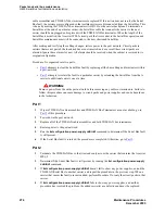
Disconnect cabinet local cable connector J2F from the P2F connector on top of the power filter.
4
Disconnect cable connector J2 from the P2 connector on the fan assembly.
5
Loosen the power filter mounting screws using a 5/16” nut driver and remove the filter.
CAUTION:
Failure to connect the J2 connector on the fan assembly can damage the fan alarm circuits.
6
Connect the J2 cable connector of the replacement power filter to the P2 connector on the fan
assembly.
7
Mount the new power filter on the screws and tighten.
8
Connect cabinet local cable connector J2F to the P2F connector on the top of the power filter.
9
The fans should start rotating after a 4 second delay.
Replacing the temperature sensor
The top temperature sensors are located at the top rear of the cabinet in some cabinets. On these cabinets,
the removable media shelf is located on the rear door, at the bottom.
1
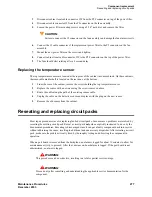
From the rear of the cabinet, remove the screws holding the top temperature sensor.
2
Replace the sensor with a new one using the screws removed above.
3
Route the cable along the path of the existing sensor cable.
4
Unplug the cable on the defective sensor and replace with the plug on the new sensor.
5
Remove the old sensor from the cabinet.
Reseating and replacing circuit packs
Most repair procedures involve replacing faulted circuit packs. In some cases, problems are resolved by
reseating the existing circuit pack. Reseat a circuit pack only when explicitly instructed to do so by the
documented procedures. Reseating is discouraged since it can put a faulty component back into service
without addressing the cause, resulting in additional and unnecessary dispatches. After reseating a circuit
pack, make sure the problem is really fixed by thoroughly testing and observing the component in
operation.
When a port board is removed from the backplane, no alarm is logged for about 11 minutes to allow for
maintenance activity to proceed. After that, a minor on-board alarm is logged. If the port board is not
administered, no alarm is logged.
!
WARNING:
This procedure can be destructive, resulting in a total or partial service outage.
!
WARNING:
Proceed only after consulting and understanding the applicable service documentation for the
component.
Summary of Contents for CMC1
Page 1: ...Maintenance Procedures 555 245 103 Issue 1 1 December 2003 ...
Page 14: ...Contents 14 Maintenance Procedures December 2003 ...
Page 416: ...Additional maintenance procedures IP Telephones 416 Maintenance Procedures December 2003 ...
Page 426: ...Index X 426 Maintenance Procedures December 2003 ...


