


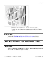


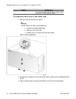

To position the 201i server on the switch shelf
1. Ensure that no cables are connected to the slots in which you are installing the 201i
server.
2. Open the lock latches at the top and bottom of the 201i server faceplate.
Note:
When you open the top lock latch, you break the yellow backplane warning label,
if it has not been removed. You must move the secondary backplane connector
before you install the 201i server. For details, see
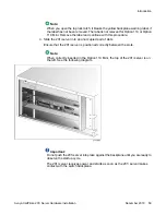
3. Slide the 201i server into an unoccupied pair of slots.
Ensure that the 201i server is positioned correctly between the slots.
Important:
Do not push the 201i server into place against the backplane until you are ready to
observe the startup cycle.
The 201i server receives power and starts as soon as the 201i server makes
contact with the switch backplane.
4. Connect the low-profile right-angle SCSI cable connector to the SCSI connector on
the 201i server faceplate.
What is next?
Continue with
Removing the backplane (tip and ring) cables
Removing the backplane (tip and ring) cables
Introduction
You must remove the Meridian 1 backplane (tip and ring) cables that are associated with the
slots occupied by the 201i server so that you can install the following cables:
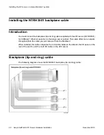
• NTRH3501 backplane (tip and ring) cable
Installing the 201i server in a large Meridian 1 system
44 Avaya CallPilot
®
201i Server Hardware Installation
December 2010