


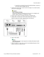


4. Connect the power cord for each device.
5. Power up the devices.
What is next?
Continue with
Connecting the 201i server to the switch, ELAN subnet , and Avaya server
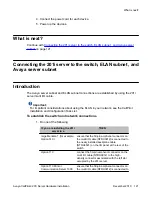
Connecting the 201i server to the switch, ELAN subnet , and
Avaya server subnet
Introduction
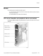
The Avaya server subnet and ELAN subnet connections are established by using the 201i
server multi I/O cable.
Important:
For important considerations about using the ELAN in your network, see the CallPilot
Installation and Configuration Task List.
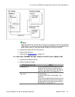
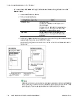
To establish the switch and network connections
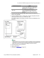
1. Do one of the following:
IF you are installing the 201i
server in a
THEN
large Meridian 1 (for example,
Option 51C)
ensure that the 50-pin amphenol connector on
the multi I/O cable (NTRH0912) is connected to
the newly installed backplane cable
(NTRH3501) on the I/O panel at the rear of the
switch.
Option 11C
connect the 50-pin amphenol connector on the
multi I/O cable (NTRH0912) to the high-
density connector associated with the left slot
occupied by the 201i server.
Option 11C Mini or
Communication Server 1000
ensure that the 50-pin amphenol connector on
the multi I/O cable (NTRH0912) is connected to
What is next?
Avaya CallPilot
®
201i Server Hardware Installation
December 2010 121