Avaya 4900 Series Installation Job Aid Download Page 3

Warning:

Disconnecting the power cord is the only way to turn off power to this device. Always connect
the power cord in a location that can be reached quickly and safely in case of an emergency.

Warning:

Fiber optic equipment can emit laser or infrared light that can injure your eyes. Never look into
an optical fiber or connector port. Always assume that fiber optic cables are connected to a light
source.

Caution:

Risk of explosion if battery is replaced by an incorrect type. Dispose of used batteries according
to the instructions.

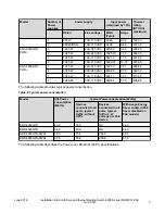
Technical specifications

The following table provides the technical specifications for the switches in this series. Ensure that
the area where you install the switch and where it operates meets these requirements.

Warning:

To avoid bodily injury from hazardous electrical shock and current, never remove the top of the
device. No user-serviceable components are inside.

Table 1: Physical specifications

Height

4.4 cm – 1RU

Width

17.32 inch (440 mm or 44 cm) - 19 inch rack
mountable

Depth

18.89 inch (480 mm or 48 cm)

Weight (switch weight with one PSU. Where, PSU
approximately weighs 1.6 kg)

• ERS4926GTS: 7.2 kg

• ERS4926GTS-PWR+: 7.9 kg

• ERS4950GTS: 7.3 kg

• ERS4950GTS-PWR+: 8.0 kg

Table 2: Environmental specifications

Operating Temperature

0° and 50° C (32° and 106° F)

Storage Temperature

–40°C to 85°C (-40°F to 185°F)

Table continues…

June 2016

Installation Job Aid for Avaya Ethernet Routing Switch 4900 Series (NN47212-302,

ver 02.01)

3

Summary of Contents for 4900 Series

Page 1: ... reseller and you need assistance contact the technical support staff for that distributor or reseller Notices Notice paragraphs alert you about issues that require your attention The following paragraphs describe the types of notices used in this guide Note Notes provide tips and useful information regarding the installation and operation of Avaya products Electrostatic alert ESD ESD notices prov...

Page 2: ...nly Read and follow all warning notices and instructions marked on the product or included in the documentation Voltage This equipment relies on the building s installation for overcurrent protection Ensure that a fuse or circuit breaker no larger than 120 VAC 20 A or 240 VAC 16 A is used on the phase conductors Caution This device is a Class A product In a domestic environment this device can cau...

Page 3: ...r the switches in this series Ensure that the area where you install the switch and where it operates meets these requirements Warning To avoid bodily injury from hazardous electrical shock and current never remove the top of the device No user serviceable components are inside Table 1 Physical specifications Height 4 4 cm 1RU Width 17 32 inch 440 mm or 44 cm 19 inch rack mountable Depth 18 89 inc...

Page 4: ... ventilation Cables should be dressed to prevent blocking air flow Power specifications This section provides the following power specifications for the switch AC power specifications on page 4 Typical power consumption on page 5 PoE specifications on page 6 The following table describes the AC power specifications Table 3 AC power specifications Model Number of Power supplies Power supply Input p...

Page 5: ... 11 7 55 413 56 2 1025 W 100 110 VAC 839 64 7 73 424 24 The following table provides typical power consumption Table 4 Typical power consumption Model Idle Power consumption Watts Typical Power consumption Watts Devices connected to all ports typical traffic without SFPs Devices connected to all ports typical traffic 6 W average per PoE device With Avaya Energy Saver enabled PoE Saver disabled on ...

Page 6: ...W 24 ports at 30 W 1 1025 W 100 110 VAC 30 W 720 W 24 ports at 30 W 2 1025 W 100 110 VAC 30 W 720 W 24 ports at 30 W AC power cord specifications The following section outlines the AC power cord specifications for various countries Ensure that you use the correct cord for your location Table 6 International power cord specifications Country Plug Specification Specifications Typical Plug Continenta...

Page 7: ...this section apply to all switches in Avaya Ethernet Routing Switch 4900 Series About this task Install the switch in an equipment rack Before you begin Tool requirements Phillips screwdriver to attach brackets to the switch and the switch to the rack Rack requirements Space of 2 8 inches 7 1 cm for each switch is available in an E1A or 1EC standard 19 inch 48 2 cm equipment rack and T1A 23 inch 5...

Page 8: ...the appropriate bolts to secure the switch to your specific rack before you begin Procedure 1 Ensure power is disconnected from the switch 2 Attach a bracket to each side of the switch with the included screws You have different options for front and rear mounting positions Attach the brackets in the best position for your specific equipment rack Figure 1 Front mounted rack bracket installation Ju...

Page 9: ... post equipment rack installations an optional four post rack mounting kit sold separately is available that includes adjustable rear brackets For more information see Installing Avaya Ethernet Routing Switch 4900 Series NN47212 301 June 2016 Installation Job Aid for Avaya Ethernet Routing Switch 4900 Series NN47212 302 ver 02 01 9 ...

Page 10: ...Figure 3 Front mounted rack installation June 2016 Installation Job Aid for Avaya Ethernet Routing Switch 4900 Series NN47212 302 ver 02 01 10 ...

Page 11: ...optional four post rack mounting kit sold separately is available that includes adjustable rear brackets For more information see Installing Avaya Ethernet Routing Switch 4900 Series NN47212 301 June 2016 Installation Job Aid for Avaya Ethernet Routing Switch 4900 Series NN47212 302 ver 02 01 11 ...

Page 12: ...Figure 5 Rack mount attachment screws June 2016 Installation Job Aid for Avaya Ethernet Routing Switch 4900 Series NN47212 302 ver 02 01 12 ...

Page 13: ...tallation by connecting power and network connections to the switch Connecting AC power About this task The Ethernet Routing Switch 4900 Series does not have a power switch When you connect the AC power cord to a suitable AC power outlet the switch powers up immediately Before you begin Ensure to use the correct power cord for the switch and power supply Procedure 1 Connect the AC power cord to th...

Reviews: