Duplex signaling
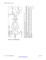
Duplex (DX) signaling makes use of the voice transmission leads for signaling as well as for
voice transmission.
For descriptive purposes, the lead pair Tip B/Ring B is designated the signaling pair. The other
pair Tip A/Ring A conducts current in the opposite direction to balance the overall current flow
between the near and far ends. During signaling, current flows through both Tip B and Ring B
leads in the same direction.
Table 183: DX signaling - outgoing calls with originating party release
on page 448 and
184: DX signaling - incoming calls with originating party release
on page 448 show call-
connection and take-down sequencing for DX signaling.
Table 185: DX signaling - outgoing
calls with originating party release on tandem connections
on page 449 and
signaling - incoming calls with originating party release on tandem connections
on page 450
show sequencing where the E and M Trunk card is used in a tandem PBX.
Table 183: DX signaling - outgoing calls with originating party release
Condition
Current in signaling
lead
State of trunk
detector
Idle
No current flow
High
Seizure (dial tone from far-end: far-end ready
for digits)
Current flow
High
Digits
Current flow
interrupted for each
pulse
High
Far-end answers
No current flow
Low
Far-end on hook first
Current flow
High
Network taken down and trunk idled when
near-end goes on hook
No current flow
High
Near-end on hook first, network taken down Current flow
Low
Far-end on hook, trunk idled
No current flow
High
Table 184: DX signaling - incoming calls with originating party release
Condition
Current in signaling
lead
State of trunk
detector
Idle
No current flow
High
Seizure (dial tone to far-end: near-end ready
for digits)
Current flow
Low
NT8D15 E and M Trunk card
448 Circuit Card Reference
July 2011
Summary of Contents for 1000 Series
Page 1: ...Circuit Card Reference Nortel Communication Server 1000 7 0 NN43001 311 04 04 July 2011 ...
Page 20: ...20 Circuit Card Reference July 2011 ...
Page 30: ...Introduction 30 Circuit Card Reference July 2011 Comments infodev avaya com ...
Page 116: ...Option settings 116 Circuit Card Reference July 2011 Comments infodev avaya com ...
Page 143: ...Figure 25 CP PIV card front Physical description Circuit Card Reference July 2011 143 ...
Page 148: ...NT4N39AA CP Pentium IV Card 148 Circuit Card Reference July 2011 Comments infodev avaya com ...
Page 287: ...Figure 86 Clock Controller Option 3 Operation Circuit Card Reference July 2011 287 ...
Page 302: ...NT5K21 XMFC MFE card 302 Circuit Card Reference July 2011 Comments infodev avaya com ...
Page 346: ...NT6D80 MSDL card 346 Circuit Card Reference July 2011 Comments infodev avaya com ...
Page 353: ...Figure 96 NTDK16 DLC Functional description Circuit Card Reference July 2011 353 ...
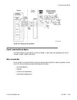
Page 461: ...Figure 147 Paging trunk operation Applications Circuit Card Reference July 2011 461 ...
Page 462: ...NT8D15 E and M Trunk card 462 Circuit Card Reference July 2011 Comments infodev avaya com ...
Page 500: ...NTAK09 1 5 Mb DTI PRI card 500 Circuit Card Reference July 2011 Comments infodev avaya com ...
Page 512: ...NTAK10 2 0 Mb DTI card 512 Circuit Card Reference July 2011 Comments infodev avaya com ...
Page 534: ...NTAK79 2 0 Mb PRI card 534 Circuit Card Reference July 2011 Comments infodev avaya com ...
Page 550: ...NTBK22 MISP card 550 Circuit Card Reference July 2011 Comments infodev avaya com ...
Page 560: ...NTBK50 2 0 Mb PRI card 560 Circuit Card Reference July 2011 Comments infodev avaya com ...
Page 595: ...Figure 165 MGC block diagram Introduction Circuit Card Reference July 2011 595 ...
Page 662: ...NTRB21 DTI PRI DCH TMDI card 662 Circuit Card Reference July 2011 Comments infodev avaya com ...
Page 668: ...NTVQ01xx Media Card 668 Circuit Card Reference July 2011 Comments infodev avaya com ...
Page 700: ......

