


- programmed configuration status
• receipt and implementation of card configuration:
- programming of the CODECs
- enabling/disabling of individual units or entire card
- programming of input/output interface control circuits for administration of line
interface unit operation
- enabling/disabling of an interrupted dial tone to indicate call waiting
- maintenance diagnostics
- transmission loss levels
Card LAN interface
Maintenance data is exchanged with the CPU over a dedicated asynchronous serial network
called the Card LAN link. The Card LAN link is described in the section
on page 35.
The NT1R20 OPS analog line card has the capability of providing an interrupted dial tone to
indicate that a message is waiting or that call forwarding is enabled. The line card (optionally)
receives messages stating that these conditions exist over the Card LAN Interface and
interrupts the dial tone when either of these conditions are detected.
Software service changes
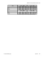
Individual line interface units on the NT1R20 OPS analog line card are configured to either
OPS (for OPS application) or On-premises Station (ONS) (for ONS application) Class of
Service (CLS) in the Analog (500/2500-type) Telephone Administration program LD 10. See
Table 52: OPS analog line card configuration
LD 10 is also used to select unit terminating impedance and balance network impedance at
the TIMP and BIMP prompts, respectively.
The message waiting interrupted dial tone and call forward reminder tone features are enabled
by entering data into the customer data block using LD 15.
See
Software Input/Output Reference — Administration
(NN43001-611) for LD 10 and LD 15
service change instructions.
Table 52: OPS analog line card configuration
Application
On-premise station (ONS)
Off-premise station (OPS)
Class of
service
ONS
OPS
Functional description
Circuit Card Reference
July 2011 123
Summary of Contents for 1000 Series
Page 1: ...Circuit Card Reference Nortel Communication Server 1000 7 0 NN43001 311 04 04 July 2011 ...
Page 20: ...20 Circuit Card Reference July 2011 ...
Page 30: ...Introduction 30 Circuit Card Reference July 2011 Comments infodev avaya com ...
Page 116: ...Option settings 116 Circuit Card Reference July 2011 Comments infodev avaya com ...
Page 143: ...Figure 25 CP PIV card front Physical description Circuit Card Reference July 2011 143 ...
Page 148: ...NT4N39AA CP Pentium IV Card 148 Circuit Card Reference July 2011 Comments infodev avaya com ...
Page 287: ...Figure 86 Clock Controller Option 3 Operation Circuit Card Reference July 2011 287 ...
Page 302: ...NT5K21 XMFC MFE card 302 Circuit Card Reference July 2011 Comments infodev avaya com ...
Page 346: ...NT6D80 MSDL card 346 Circuit Card Reference July 2011 Comments infodev avaya com ...
Page 353: ...Figure 96 NTDK16 DLC Functional description Circuit Card Reference July 2011 353 ...
Page 461: ...Figure 147 Paging trunk operation Applications Circuit Card Reference July 2011 461 ...
Page 462: ...NT8D15 E and M Trunk card 462 Circuit Card Reference July 2011 Comments infodev avaya com ...
Page 500: ...NTAK09 1 5 Mb DTI PRI card 500 Circuit Card Reference July 2011 Comments infodev avaya com ...
Page 512: ...NTAK10 2 0 Mb DTI card 512 Circuit Card Reference July 2011 Comments infodev avaya com ...
Page 534: ...NTAK79 2 0 Mb PRI card 534 Circuit Card Reference July 2011 Comments infodev avaya com ...
Page 550: ...NTBK22 MISP card 550 Circuit Card Reference July 2011 Comments infodev avaya com ...
Page 560: ...NTBK50 2 0 Mb PRI card 560 Circuit Card Reference July 2011 Comments infodev avaya com ...
Page 595: ...Figure 165 MGC block diagram Introduction Circuit Card Reference July 2011 595 ...
Page 662: ...NTRB21 DTI PRI DCH TMDI card 662 Circuit Card Reference July 2011 Comments infodev avaya com ...
Page 668: ...NTVQ01xx Media Card 668 Circuit Card Reference July 2011 Comments infodev avaya com ...
Page 700: ......