background image

User’s  Manual   

EAX-C236KP 

User’s  Manual   


23 


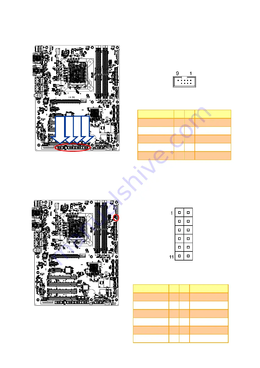
2.3.7 

Serial port 3/4/5/6 connector (JCOM3/4/5/6) 


Signal 

PIN  PIN 

Signal 

RXD 

DCD 

DTR 

TXD 

DSR 

GND 

CTS 

RTS 

NC 

10 

RI 


2.3.8 

General purpose I/O connector (JDIO1) 


Signal 

PIN  PIN 

Signal 

DI0 

DO0 

DI1 

DO1 

DI2 

DO2 

DI3 

DO3 

SMB_CLK_9555 

10  SMB_DATA_9555 

GND 

11 

12 

+5V 


JCO

M3


JCO

M4


JCO

M5


JCO

M6


Summary of Contents for EAX-C236KP

Page 1: ...Part No E2047AKBX00R EAX C236KP Intel Core Processors with Intel C236 ATX Motherboard User s Manual 1st Ed 06 September 2017 ...

Page 2: ...THE USER WILL BE REQUIRED TO CORRECT THE INTERFERENCE AT HIS OWN EXPENSE Notice This guide is designed for experienced users to setup the system within the shortest time For detailed information please always refer to the electronic user s manual Copyright Notice Copyright 2017 Avalue Technology Inc ALL RIGHTS RESERVED No part of this document may be reproduced copied translated or transmitted in ...

Page 3: ...nably expected to cause the failure of the life support device or system or to affect its safety or effectiveness A Message to the Customer Avalue Customer Services Each and every Avalue s product is built to the most exacting specifications to ensure reliable performance in the harsh and demanding conditions typical of industrial environments Whether your new Avalue device is destined for the lab...

Page 4: ...placement materials service time and freight Please consult your dealer for more details If you think you have a defective product follow these steps 1 Collect all the information about the problem encountered For example CPU type and speed Avalue s products model name hardware BIOS revision number other hardware and software used etc Note anything abnormal and list any on screen messages you get ...

Page 5: ...OM2A 22 2 3 6 COM2 RS485 422 connector JCOM2B 22 2 3 7 Serial port 3 4 5 6 connector JCOM3 4 5 6 23 2 3 8 General purpose I O connector JDIO1 23 2 3 9 SGPIO connector JSGPIO1 24 2 3 10 ATX Power connector ATXPWR1 24 2 3 11 Power connector ATX12V1 25 2 3 12 SMBus connector JSMB1 25 2 3 13 USB connector 1 JUSB1 26 2 3 14 USB connector 2 JUSB2 26 2 3 15 USB connector 4 JUSB4 27 2 3 16 Battery connect...

Page 6: ...ration 41 3 6 2 1 1 CPU Power Management Control 42 3 6 2 2 PCH FW Configuration 43 3 6 2 2 1 Firmware Update Configuration 44 3 6 2 2 2 OEM Flags Settings 44 3 6 2 3 Trusted Computing 45 3 6 2 4 APCI Settings 45 3 6 2 5 S5 RTC Wake Settings 46 3 6 2 6 Super IO Configuration 48 3 6 2 6 1 Serial Port 1 Configuration 49 3 6 2 6 2 Serial Port 2 Configuration 50 3 6 2 6 3 Serial Port 3 Configuration 5...

Page 7: ...6 3 2 2 SATA And RST Configuration 71 3 6 3 2 3 HD Audio Configuration 72 3 6 4 Security 73 3 6 4 1 Secure Boot menu 73 3 6 4 1 1 Key Management 74 3 6 5 Boot 75 3 6 6 Save and exit 76 3 6 6 1 Save Changes and Reset 76 3 6 6 2 Discard Changes and Reset 76 3 6 6 3 Restore Defaults 76 3 6 6 4 Launch EFI Shell from filesystem device 76 4 Drivers Installation 77 4 1 Install Chipset Driver 78 4 2 Insta...

Page 8: ... should open the PC chassis Caution Always ground yourself to remove any static charge before touching the CPU card Modern electronic devices are very sensitive to static electric charges As a safety precaution use a grounding wrist strap at all times Place all electronic components in a static dissipative surface or static shielded bag when they are not in the chassis 1 2 Packing List Before you ...

Page 9: ...User s Manual EAX C236KP User s Manual 9 1 3 Document Amendment History Revision Date By Comment 1st September 2017 Avalue Initial Release ...

Page 10: ...al carefully before attempting to set up EAX C236KP or change the standard configurations Whilst all the necessary information is available in this manual we would recommend that unless you are confident you contact your supplier for guidance Please be aware that it is possible to create configurations within the CMOS RAM that make booting impossible If this should happen clear the CMOS settings s...

Page 11: ...W Status Monitor CPU temperature monitoring Voltages monitoring CPU fan speed control Expansion 1 x PCI e x 16 1 x PCI e x 4 1 x PCI e x 1 4 x PCI 1 x M 2 2230 KeyA Slot support WiFi module 1 x SIM card slot 1 x Full Size Mini PCIe with mSATA Support SATA III S3 S4 Yes S0 S3 S4 S5 Display Chipset Intel C236 Express chipset Resolution VGA 2048 x 1536 50 Hz HDMI 4096 x 2160 24 Hz 2560 x 1600 60 Hz D...

Page 12: ... 10 pin pitch 2 0mm connector for USB 3 0 USB Wake up by BIOS Setting 1 x 1 x 4 pin pitch 2 54mm CPU fan connector with smart fan function supported 1 x 1 x 4 pin pitch 2 54mm System fan connector with smart fan function supported 1 x 1 x 3 pin pitch 2 54mm System fan connector 1 x 2 x 5 pin pitch 2 54mm connector for front panel 1 x 2 x 10 pin pitch 2 54mm connector for Auxiliary panel 1 x 4 pin ...

Page 13: ...5 with Dual deck USB 3 0 connector 1 x VGA 1 x DP 1 x HDMI COM1 support RS 232 DB9 connector Pin 9 with 5V 12V RI Supported 1 x Line out 1 x Mic In 1 x Line in PS 2 KB MS USB2 0 connector Mechanical Environmental Power Requirement 12V 5V 5VSB 3 3V 12V ACPI Single power ATX Support S0 S3 S4 S5 Power on Type AT ATX mode Operating Temp 0 60 C 32 140 F Storage Temp 40 75 C Operating Humidity 0 90 rela...

Page 14: ...EAX C236KP User s Manual 14 EAX C236KP User s Manual ...

Page 15: ...User s Manual EAX C236KP User s Manual 15 1 6 Architecture Overview Block Diagram The following block diagram shows the architecture and main components of EAX C236KP ...

Page 16: ...EAX C236KP User s Manual 16 EAX C236KP User s Manual 2 Hardware Configuration ...

Page 17: ...User s Manual EAX C236KP User s Manual 17 2 1 Product Overview ...

Page 18: ...rd disk drives a keyboard or floppy drives In addition the board has a number of jumpers that allow you to configure your system to suit your application If you have any doubts about the best hardware configuration for your application contact your local distributor or sales representative before you make any changes The following tables list the function of each of the board s jumpers and connect...

Page 19: ...rd mouse connector 2 x USB 2 0 connector JKBMS1 PS 2 keyboard mouse connector 6 x 1 wafer pitch 2 50 mm LAN1 2 2 x RJ 45 with Dual deck USB 3 0 connector JUSB1 USB connector 1 10 x 2 wafer pitch 2 00mm JUSB2 USB connector 2 5 x 1 header pitch 2 54mm JUSB3 USB connector 3 JUSB4 USB connector 4 5 x 2 header pitch 2 54mm JLPC1 LPC connector 5 x 2 header pitch 2 00mm PCIE1 2 3 PCIe slot 1 2 3 PCI1 2 3...

Page 20: ...236KP User s Manual 20 EAX C236KP User s Manual 2 3 Setting Jumpers Connectors 2 3 1 Serial port 1 pin9 signal select JRI1 Default Ring 5V 12V 2 3 2 Serial port 2 pin9 signal select JRI2 Default Ring 5V 12V ...

Page 21: ...User s Manual EAX C236KP User s Manual 21 2 3 3 AT ATX Power Mode Select JATATX1 Default AT ATX 2 3 4 Clear CMOS JCMOS1 Default Protect Clear CMOS ...

Page 22: ...236KP User s Manual 2 3 5 Serial port 2 connector JCOM2A Signal PIN PIN Signal RXD 2 1 DCD DTR 4 3 TXD DSR 6 5 GND CTS 8 7 RTS 9 RI 2 3 6 COM2 RS485 422 connector JCOM2B Signal PIN PIN Signal 485TX 1 2 422RX 485TX 3 4 422RX 5V 5 6 GND ...

Page 23: ...or JCOM3 4 5 6 Signal PIN PIN Signal RXD 2 1 DCD DTR 4 3 TXD DSR 6 5 GND CTS 8 7 RTS NC 10 9 RI 2 3 8 General purpose I O connector JDIO1 Signal PIN PIN Signal DI0 1 2 DO0 DI1 3 4 DO1 DI2 5 6 DO2 DI3 7 8 DO3 SMB_CLK_9555 9 10 SMB_DATA_9555 GND 11 12 5V JCOM3 JCOM4 JCOM5 JCOM6 ...

Page 24: ...y Enterprise RSTe Driver Signal PIN PIN Signal GND 1 2 GND SGIO_LOAD 3 4 SGIO_DATOUT0 SGIO_CLK 5 6 SGIO_DATOUT1 2 3 10 ATX Power connector ATXPWR1 Signal PIN PIN Signal 3 3V 12 24 GND 12V 11 23 5V 12V 10 22 5V V5SB 9 21 5V ATX_PWRGD 8 20 5V GND 7 19 GND 5V 6 18 GND GND 5 17 GND 5V 4 16 ATX_PSON GND 3 15 GND 3 3V 2 14 12V 3 3V 1 13 3 3V ...

Page 25: ...6KP User s Manual 25 2 3 11 Power connector ATX12V1 Signal PIN PIN Signal 12V 5 1 GND 12V 6 2 GND 12V 7 3 GND 12V 8 4 GND 2 3 12 SMBus connector JSMB1 Signal PIN SMB_CLK_MAIN 1 SMB_DATA_MAIN 2 SMB_ALERT _MAIN 3 GND 4 3 3V 5 ...

Page 26: ...P14 USB_R_DP13 9 12 USB_R_DN14 USB_R_DN13 8 13 GND GND 7 14 SS_USB_TXP_C_6 SS_USB_TXP_C_5 6 15 SS_USB_TXN_C_6 SS_USB_TXN_C_5 5 16 GND GND 4 17 SS_USB_RXP_C_6 SS_USB_RXP_C_5 3 18 SS_USB_RXN_C_6 SS_USB_RXN_C_5 2 19 USBVCC_DE USBVCC_DE 1 2 3 14 USB connector 2 JUSB2 Signal PIN USBVCC56 1 USB_R_DN5 2 USB_R_DP5 3 GND 4 GND 5 ...

Page 27: ...P User s Manual 27 2 3 15 USB connector 4 JUSB4 Signal PIN PIN Signal USBVCC_BC 1 2 USBVCC_BC USB_R_DN12 3 4 USB_R_DN11 USB_R_DP12 5 6 USB_R_DP11 GND 7 8 GND 10 NC 2 3 16 Battery connector JBAT1 Signal PIN RTC_VBAT_1 1 GND 2 ...

Page 28: ...MIC2_JD GND 7 LINE2_LIN 9 10 LINE2_JD 2 3 17 1 Signal Description Audio connector JAUDIO1 Signal Signal Description LINE2_JD AUDIO IN LINE_RIN LIN sense pin MIC2_JD MIC IN MIC_RIN LIN sense pin 2 3 18 LPC connector JLPC1 Signal PIN PIN Signal LPC_AD0_R 1 2 3 3V LPC_AD1_R 3 4 BUF_PLT_RST LPC_AD2_R 5 6 LPC_FRAME _R LPC_AD3_R 7 8 LPC_CLK LPC_SERIRQ_R 9 10 GND ...

Page 29: ...6KP User s Manual 29 2 3 19 SPI connector JSPI1 Signal PIN PIN Signal 3 3V 1 2 GND SSPI_CS0 _R 3 4 SSPI_SCLK_R SSPI_SO_R 5 6 SSPI_SI_R SSPI_HOLD 0 7 2 3 20 Speaker connector JSPK1 Signal PIN SPK_L 1 SPK_L 2 SPK_R 3 SPK_R 4 ...

Page 30: ...KP User s Manual 2 3 21 Miscellaneous setting connector JFP1 Signal PIN PIN Signal HDD_LED 1 2 PWR_LED HDD_LED 3 4 PWE_LED RSET_BTN 5 6 PWRBTN GND 7 8 GND NC 9 2 3 22 CPU fan connector CPUFAN1 Signal PIN GND 1 12V 2 CPUFANIN 3 CPUFANOUT 4 ...

Page 31: ...ser s Manual EAX C236KP User s Manual 31 2 3 23 System fan connector 1 SYSFAN1 Signal PIN GND 1 12V 2 SYSFANIN1 3 SYSFANOUT1 4 2 3 24 System fan connector 2 SYSFAN3 Signal PIN GND 1 12V 2 SYS_FAN_IN_2 3 ...

Page 32: ...C236KP User s Manual 32 EAX C236KP User s Manual 2 3 25 PS 2 keyboard mouse connector JKBMS1 Signal PIN MSCK 6 5V 5 GND 4 MSDT 3 KBDT 2 KBCK 1 2 3 26 S PDIF connector JSPDIF1 Signal PIN 5V 1 SPDIF_O 3 GND 4 ...

Page 33: ...JBZ1 Signal PIN 5V 1 NC 2 NC 3 BEEP 4 2 3 28 LPT connector LPT1 Signal PIN PIN Signal PT STB 1 2 PT_AFD PTD0 3 4 ERR PTD1 5 6 PT_PAR_INIT PTD2 7 8 PT_SLIN PTD3 9 10 GND PTD4 11 12 GND PTD5 13 14 GND PTD6 15 16 GND PTD7 17 18 GND ACK 19 20 GND BUSY 21 22 GND PE 23 24 GND SLCT 25 ...

Page 34: ...FRONT_LAN1_LINK1000 FRONT_LAN2_ACT 17 18 FRONT_LAN2_LINK100 GND 19 20 FRONT_LAN2_LINK1000 2 3 30 Gigabit LAN RJ 45 connector LAN1 2 Note This port allows Gigabit connection to a Local Area Network LAN through a network hub Refer to the table below for the LAN port LED indications ACT LINK LED SPEED LED Status Description Status Description OFF No Light OFF 10Mbps connection Orange Linked Green 100...

Page 35: ...User s Manual EAX C236KP User s Manual 35 3 BIOS Setup ...

Page 36: ...n control over to the operating system While the BIOS is in control the Setup program can be activated in one of two ways By pressing Del or F2 immediately after switching the system on or By pressing the Del or F2 key when the following message appears briefly at the left top of the screen during the POST Power On Self Test Press Del or F2 to enter SETUP If the message disappears before you respo...

Page 37: ...Quit and not save changes into NVRAM Status Page Setup Menu and Option Page Setup Menu Exit current page and return to Main Menu key Increase the numeric value or make changes key Decrease the numeric value or make changes F1 key General help only for Status Page Setup Menu and Option Page Setup Menu F2 key Previous Values F3 key Optimized defaults F4 key Save Exit Setup Navigating Through The Men...

Page 38: ...ur computer no longer is able to boot the AMI BIOS supports an override to the NVRAM settings which resets your system to its defaults The best advice is to only alter settings which you thoroughly understand To this end we strongly recommend that you avoid making any changes to the chipset defaults These defaults have been carefully chosen by both BIOS Vendor and your systems manufacturer to prov...

Page 39: ...ear on the screen The Main Menu allows you to select from several setup functions and exit choices Use the arrow keys to select among the items and press Enter to accept and enter the sub menu 3 6 1 Main Menu This section allows you to record some basic hardware configurations in your computer and set the system clock ...

Page 40: ...ystem date Manually enter the day month and year 3 6 1 3 System Time Use the system time option to set the system time Manually enter the hours minutes and seconds Note The BIOS setup screens shown in this chapter are for reference purposes only and may not exactly match what you see on your screen Visit the Avalue website www avalue com tw to download the latest product and BIOS information ...

Page 41: ...operation through the following sub menus 3 6 2 1 CPU Configuration Item Options Description Intel VMX Virtualization Technology Disabled Enabled Default When enabled a VMM can utilize the additional hardware capabilities provided by Vanderpool Technology Active Processor Cores All Default 1 Number of cores to enable in each processor package ...

Page 42: ...able Disable processor Turbo Mode requires EMTTM enabled too AUTO means enabled unless max turbo ratio is bigger than 16 SKL A0 W A C States Disabled Enabled Default Enable Disable CPU Power Management Allows CPU to go to C states when it s not 100280215848tilized Enhanced C states Disabled Enabled Default Enable Disable C1E When enabled CPU will switch to minimum speed when all cores enter C Stat...

Page 43: ...figuration Item Options Description ME State Disabled Enabled Default When Disabled ME will be put into ME Temporarily Disabled Mode AMT BIOS Features Disabled Enabled Default When disabled AMT BIOS Features are no longer supported and user is no longer able to access MEBx Setup Note This option does not disable Manageability Features in FW ...

Page 44: ...guration Item Option Description Me FW Image Re Flash Disabled Default Enabled Enable Disable Me FW Image Re Flash function 3 6 2 2 2 OEM Flags Settings Item Option Description Unconfigure ME Disabled Default Enabled OEMFlag Bit 15 Unconfigure ME with resetting MEBx password to default ...

Page 45: ...usted Computing Item Options Description Security Device Support Disable Enable Default Enables or Disables BIOS support for security device O S will not show Security Device TCG EFI protocol and INT1Ainterface will not be available 3 6 2 4 APCI Settings ...

Page 46: ... ErP Deep S5 Function Allow BIOS switching off peripheral power delivery at S5 state Pwr On After PWR Fail Always Off Default Always On Keep Last state Specify what state to go to when power is re applied after a power failure G3 state Watch Dog Disabled Default 30 sec 40 sec 50 sec 1 min 2 min 10 min 30 min Select Watch Dog Timer WDT Mode Wake Up by Ring Disabled Enabled Default Enable Disable sy...

Page 47: ...on Wake system from S5 Disabled Fixed Time Default Dynamic Time Enable or disable System wake on alarm event Select Fixed Time system will wake on the hr min sec specified Select Dynamic Time System will wake on the current time Increase minute s Wake up day of week Disabled Monday Friday Monday Saturday Default Wake up day of week selection Disabled select day of month Monday Friday only Monday S...

Page 48: ... wake on alarm event Select Fixed Time system will wake on the hr min sec specified Select Dynamic Time System will wake on the current time Increase minute s Wake up minute increase 1 5 1 5 3 6 2 6 Super IO Configuration You can use this item to set up or change the Super IO configuration for serial ports Please refer to 3 6 2 6 1 3 6 2 6 7 for more information ...

Page 49: ...ameters of Serial Port 3 COMC Serial Port 4 Configuration Set Parameters of Serial Port 4 COMD Serial Port 5 Configuration Set Parameters of Serial Port 5 COME Serial Port 6 Configuration Set Parameters of Serial Port 6 COMF Parallel Port Configuration Set Parameters of Parallel Port LPT LPTE 3 6 2 6 1 Serial Port 1 Configuration Item Option Description Serial Port Enabled Default Disabled Enable ...

Page 50: ...3 6 2 6 2 Serial Port 2 Configuration Item Option Description Serial Port Enabled Default Disabled Enable or Disable Serial Port COM UART 232 422 485 RS232 Default RS422 RS485 Set COM Port as RS232 RS422 or RS485 mode 3 6 2 6 3 Serial Port 3 Configuration ...

Page 51: ... Description Serial Port Enabled Default Disabled Enable or Disable Serial Port COM 3 6 2 6 4 Serial Port 4 Configuration Item Option Description Serial Port Enabled Default Disabled Enable or Disable Serial Port COM 3 6 2 6 5 Serial Port 5 Configuration ...

Page 52: ...User s Manual Item Option Description Serial Port Enabled Default Disabled Enable or Disable Serial Port COM 3 6 2 6 6 Serial Port 6 Configuration Item Option Description Serial Port Enabled Default Disabled Enable or Disable Serial Port COM ...

Page 53: ...t Configuration Item Option Description Parallel Port Enabled Default Disabled Enable or Disable Parallel Port LPT LPTE Device Mode STD Printer Mode Default SPP Mode EPP 1 9 and SPP Mode EPP 1 7 and SPP Mode Change the Printer Port mode 3 6 2 7 NCT6106D H W Monitor ...

Page 54: ...U Fan Mode Manual Default SmartFan IV Smart Fan Mode Selection Manual Mode No Smart Fan SmartFan IV Mode CPU Fan Manual Duty 0 255 CPU Fan manual output duty 0 to 255 SYSFAN1 Mode Manual SmartFan IV Default Smart Fan Mode Selection Manual Mode No Smart Fan SmartFan IV Mode 3 6 2 8 Serial Port Console Redirection ...

Page 55: ...al port transmission speed The speed must be matched on the other side Long or noisy lines may require lower speeds Data Bits 7 8 Default Data Bits Parity None Default Even Odd Mark Space A parity bit can be sent with the data bits to detect some transmission errors Even parity bit is 0 if the num of 1 s in the data bits is even Odd parity bit is 0 if num of 1 s in the data bits is odd Mark Parity...

Page 56: ...rt for ANSI VT100 terminals Recorder Mode Disabled Default Enabled With this mode enabled only text will be sent This is to capture Terminal data Resolution 100 31 Disabled Enabled Default Enables or disables extended terminal resolution Legacy OS Redirection Resolution 80 24 Default 80 25 On Legacy OS the Number of Rows and Columns supported redirection Putty KeyPad VT100 Default LINUX XTERMR6 SC...

Page 57: ...P Support Enabled Disabled Default Enable Ipv4 HTTP Boot Support If disabled IPV4 HTTP boot option will not be created Ipv6 PXE Support Enabled Disabled Default Enable Ipv6 PXE Boot Support If disabled IPV4 PXE boot option will not be created Ipv6 HTTP Support Enabled Disabled Default Enable Ipv6 HTTP Boot Support If disabled IPV4 HTTP boot option will not be created PXE boot wait time 0 Wait time...

Page 58: ...1 CSM Configuration Item Options Description CSM Support Enabled Default Disabled Enable Disable CSM Support GateA20 Active Upon Request Default Always UPON REQUEST GA20 can be disabled using BIOS services ALWAYS do not allow disabling GA20 this option is useful ...

Page 59: ...launch Default UEFI Legacy Controls the execution of UEFI and Legacy PXE OpROM Storage Do not launch UEFI Legacy Default Controls the execution of UEFI and Legacy Storage OpROM Other PCI devices Do not launch UEFI Legacy Default Determines OpROM execution policy for devices other than Network Storage or Video 3 6 2 12 USB Configuration The USB Configuration menu helps read USB information and conf...

Page 60: ...Controller Auto uses default value for a Root port it is 100ms for a Hub port the delay is taken form Hub descriptor Mass Storage Devices Auto Default Floppy Forced FDD Hard Disk CD ROM Mass storage device emulation type AUTO enumerates devices according to their media format Optical drives are emulated as CDROM drives with no media will be emulated according to a drive type 3 6 3 Chipset ...

Page 61: ...User s Manual EAX C236KP User s Manual 61 3 6 3 1 System Agent SA Configuration Item Option Description VT d Enabled Default Disabled VT d capability 3 6 3 1 1 Graphics Configuration ...

Page 62: ... s Manual Item Option Description Primary Display Auto Default IGFX PEG PCIE Select which of IGFX PEG PCI Graphics device should be Primary Display Or select SG for Switchable Gfx 3 6 3 1 2 DMI OPI Configuration 3 6 3 1 3 PEG Port Configuration ...

Page 63: ...lt Gen1 Gen2 Gen3 Configure PEG 0 1 0 Max Speed Program PCIe ASPM after OpROM Disabled Default Enabled Enabled PCIe ASPM will be programmed after OpROM Disabled PCIe ASPM will be programmed before OpROM 3 6 3 1 3 1 PEG Port Feature Configuration Item Option Description Detect Non Compliance Device Enabled Disabled Default Detect Non Compliance PCI Express Device in PEG ...

Page 64: ...r s Manual 64 EAX C236KP User s Manual 3 6 3 1 4 Memory Configuration 3 6 3 2 PCH IO Configuration Item Option Description LAN PHY Controller Disabled Enabled Default Enable or disable OnBoard PCH LAN PHY Controller ...

Page 65: ...ess Configuration 3 6 3 2 1 1 PCI E x4 Slot PCI E Port 1 Item Option Description PCIe x4 Slot PCI E Port 1 Enabled Default Disabled Control the PCI Express Root Port ASPM Auto Default L0sL1 Set the ASPM Level Force L0s Force all links to L0s State AUTO BIOS auto ...

Page 66: ...l wait for link to exit Detect state for enabled ports before assuming there is no device and potentially disabling the port 3 6 3 2 1 2 mPCIe mSATA Slot PCI E Port 5 Item Option Description mPCIe mSATA Slot PCI E Port 5 Enabled Default Disabled Control the PCI Express Root Port ASPM Auto L0sL1 L1 L0s Disabled Default Set the ASPM Level Force L0s Force all links to L0s State AUTO BIOS auto configu...

Page 67: ...ber of milliseconds reference code will wait for link to exit Detect state for enabled ports before assuming there is no device and potentially disabling the port 3 6 3 2 1 3 PCI E to PCI Bridge PCI E Port 6 Item Option Description PCI E to PCI Bridge PCI E Port 6 Enabled Default Disabled Control the PCI Express Root Port ...

Page 68: ...led Set the ASPM Level Force L0s Force all links to L0s State AUTO BIOS auto configure DISABLE Disables ASPM L1 Substates Disabled L1 1 L1 2 L1 1 L1 2 Default PCI Express L1 Substates settings PCIe Speed Auto Default Gen1 Gen2 Gen3 Configure PCIe Speed Detect Timeout 0 The number of milliseconds reference code will wait for link to exit Detect state for enabled ports before assuming there is no de...

Page 69: ...36KP User s Manual 69 3 6 3 2 1 5 Intel I211 LAN Chip PCI E Port 8 Item Option Description Intel I211 LAN Chip PCI E Port 8 Enabled Default Disabled Control the PCI Express Root Port 3 6 3 2 1 6 NGFF1 M 2 Slot PCI E Port 9 ...

Page 70: ... Level Force L0s Force all links to L0s State AUTO BIOS auto configure DISABLE Disables ASPM L1 Substates Disabled Default L1 1 L1 2 L1 1 L1 2 PCI Express L1 Substates settings PCIe Speed Auto Default Gen1 Gen2 Configure PCIe Speed Detect Timeout 0 The number of milliseconds reference code will wait for link to exit Detect state for enabled ports before assuming there is no device and potentially ...

Page 71: ...Item Option Description SATA Controller s Enabled Default Disabled Enable Disable SATA Device SATA Mode Selection AHCI Default RAID Determines how SATA controller s operate SATA Controller Speed Default Default Gen1 Gen2 Indicates the maximum speed the SATA controller can support ...

Page 72: ...s connected to Solid State Drive or Hard Disk Drive 3 6 3 2 3 HD Audio Configuration Item Option Description HD Audio Disabled Enabled Auto Default Control Detection of the HD Audio device Disabled HAD will be unconditionally disabled Enabled HAD will be unconditionally enabled Auto HAD will be enabled if present disabled otherwise Amplifier Gain 20 dB 26 dB Default 32 dB 36 dB Select Amplifier Ga...

Page 73: ...User s Manual EAX C236KP User s Manual 73 3 6 4 Security Administrator Password Set setup Administrator Password User Password Set User Password 3 6 4 1 Secure Boot menu ...

Page 74: ...mode is User Deployed and CSM function is disabled Secure Boot Mode Standard Custom Default Secure Boot mode selector Custom Mode enables users to change Image Execution policy and manage Secure Boot Keys 3 6 4 1 1 Key Management Item Option Description Provision Factory Defaults Enabled Disabled Default Allow to provision factory default Secure Boot keys when System is in Setup Mode ...

Page 75: ...efinite waiting Bootup NumLock State On Default Off Select the keyboard NumLock state Quiet Boot Disabled Default Enabled Enables or disables Quiet Boot option Fast Boot Disabled Default Enabled Enables or disables boot with initialization of a minimal set of devices required to launch active boot option Has no effect for BBS boot options Boot Option 1 Set the system boot order ...

Page 76: ...IOS setup program are discarded The setup program then exits and reboots the controller 3 6 6 3 Restore Defaults This option restores all BIOS settings to the factory default This option is useful if the controller exhibits unpredictable behavior due to an incorrect or inappropriate BIOS setting 3 6 6 4 Launch EFI Shell from filesystem device Attempts to Launch EFI Shell application Shellx64 efi f...

Page 77: ...er s Manual EAX C236KP User s Manual 77 4 Drivers Installation Note Installation procedures and screen shots in this section are for your reference and may not be exactly the same as shown on your screen ...

Page 78: ...alue s products automatically If not locate Index htm and choose the product from the menu left Note The installation procedures and screen shots in this section are based on Windows 10 operation system If the warning message appears while the installation process click Continue to go on Step 3 Click Install Step1 Click Next Step 4 Complete setup Step 2 Click Accept ...

Page 79: ... products automatically If not locate Index htm and choose the product from the menu left Note The installation procedures and screen shots in this section are based on Windows 10 operation system Step 3 Click Next Step 1 Click Next to continue installation Step 4 Click Next Step 2 Click Yes to accept license agreement Step 5 Click Finish to complete setup ...

Page 80: ...ow the index page of Avalue s products automatically If not locate Index htm and choose the product from the menu left Note The installation procedures and screen shots in this section are based on Windows 10 operation system Step 3 Click Next Step 1 Click Next to continue setup Step 4 Click Finish to complete the setup Step 2 Click Next ...

Page 81: ...page of Avalue s products automatically If not locate Index htm and choose the product from the menu left Note The installation procedures and screen shots in this section are based on Windows 10 operation system If the warning message appears while the installation process click Continue to go on Step1 Click Next to Install Step 2 Select Finish to complete Installation ...

Page 82: ...w the index page of Avalue s products automatically If not locate Index htm and choose the product from the menu left Note The installation procedures and screen shots in this section are based on Windows 10 operation system Step 3 Click Next Step 1 Click Install Drivers and Software Step 4 Click Next Step 2 Click Next Step 5 Click Install ...

Page 83: ...User s Manual EAX C236KP User s Manual 83 Step 6 Click Install Step 7 Click Finish to complete setup ...

Page 84: ...ow the index page of Avalue s products automatically If not locate Index htm and choose the product from the menu left Note The installation procedures and screen shots in this section are based on Windows 10 operation system Step 3 Click Next Step 1 Click Next to continue installation Step 4 Click Next Step 2 Click Next Step 5 Click Next ...

Page 85: ...User s Manual EAX C236KP User s Manual 85 Step 6 Click Finish to complete setup ...

Page 86: ...EAX C236KP User s Manual 86 EAX C236KP User s Manual 5 Mechanical Drawing ...

Page 87: ...User s Manual EAX C236KP User s Manual 87 Unit mm ...

Page 88: ...EAX C236KP User s Manual 88 EAX C236KP User s Manual Unit mm ...

Reviews: