AID-173S Quick Reference Guide
18
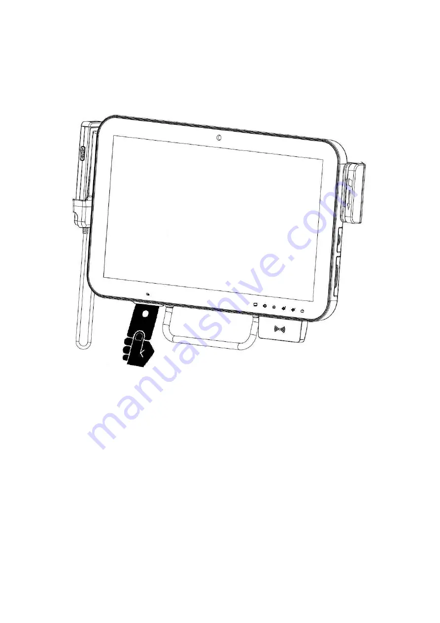
3.4 Using the Smart Card Reader
1.
Have the IC card face up.
2.
Insert the IC card into the Smart Card Reader slot.
Page 1: ...Jason Lin Part No E2017173SA1R Avalue Intelligent Display System AID 173S All In One Bedside Terminal Quick Reference Guide 1st Ed 15 October 2010 Copyright 2010 Avalue Technology Inc All Rights Reser...
Page 2: ...there is no guarantee that interference will not occur in a particular installation If this equipment does cause harmful interference to radio or television reception which can be determined by turni...
Page 3: ...ld be installed and operated with minimum distance 20cm between the radiator your body For product available in the USA Canada market only channel 1 11 can be operated Selection of other channels is n...
Page 4: ...he System 15 3 1 2 Turn OFF the System 15 3 2 Using LCD Display and Touch Screen 16 3 2 1 Adjust System Volume 16 3 2 2 Adjust LCD Display Brightness 16 3 2 3 Using Touch Screen Error Bookmark not def...
Page 5: ...eference Guide AID 173S Quick Reference Guide 5 1 AID 173S Bedside Terminal Features In this chapter you will get to know all features of our AID 173S bedside terminal 1 1 Front view 1 2 Rear Bottom v...
Page 6: ...Guide AID 173S Quick Reference Guide 6 1 1 Front view Camera Handset Magnetic Stripe Reader Smart Card Reader RFID Reader Writer 17 3 TFT LCD Touch Screen Cord 3 x USB Volume Up down Brightness Up do...
Page 7: ...k Reference Guide 7 1 2 Rear Bottom view Microphone Service Door COM1 Speaker Speaker DVI I Output Optional 1024 768 HDMI Output optional TV Antenna Input optional USB Port DC in LAN COM2 Nursing Call...
Page 8: ...e Guide AID 173S Quick Reference Guide 8 1 3 Handset Key Descriptions Activate the phone software i e Skype Nurse Call Answer Hang Up Contact List Up Contact List Down Numeric Keys Key Key Barcode Sca...
Page 9: ...instructions on how to set up AID 173S bedside terminal hardware and how to connect different cables Furthermore with provided Internet ISP setting information you will be able to connect AID 173S be...
Page 10: ...AID 173S Quick Reference Guide AID 173S Quick Reference Guide 10 2 1 Mounting Suggested Screw type for mounting Note 4 pieces of M6x10 screws VESA 75 Mounting...
Page 11: ...ID 173S Quick Reference Guide 11 2 2 Cabling 1 Power Cable 2 Ethernet RJ 45 Cable Optional 3 TV Coaxial Cable Optional Please follow below steps to connect power cable to system Coaxial connector Ethe...
Page 12: ...Reference Guide 12 2 3 System Activation Registration 1 Upon receiving your product a system activation and software registration needs be performed before you start using this system 2 Please consult...
Page 13: ...nternet 1 Use built in wireless LAN to connect to the Internet 2 Use Ethernet RJ 45 to connect to the Internet 3 Consult your Internet Service Provider ISP for software settings Note ISP IP wireless r...
Page 14: ...chapter describes in detail all features of AID 173S bedside terminal 3 1 Turn ON OFF the System 3 2 Using LCD Display and Touch Screen 3 3 Using Ear Phone and Microphone 3 4 Using Smart Card Reader 3...
Page 15: ...e your finger to touch the Power ON OFF icon 3 The Power ON OFF LED turns green 4 Your system is turned ON 3 1 2 Turn OFF the System 1 Move your finger to touch the Power ON OFF icon for about 4 secon...
Page 16: ...e your finger on the top of the Brightness Up or Brightness Down icon 2 The brightness of the LCD display will be adjusted accordingly 3 2 3 Using Touch Screen 1 To select the item on the touch screen...
Page 17: ...3S Quick Reference Guide AID 173S Quick Reference Guide 17 3 3 Using Earphone and Microphone 1 Open the rubber cover on the right side of the system 2 Insert the earphone phone or microphone into the...
Page 18: ...AID 173S Quick Reference Guide AID 173S Quick Reference Guide 18 3 4 Using the Smart Card Reader 1 Have the IC card face up 2 Insert the IC card into the Smart Card Reader slot...
Page 19: ...AID 173S Quick Reference Guide AID 173S Quick Reference Guide 19 3 5 Using Magnetic Stripe Reader 1 Have your card with the magnetic stripe facing outside 2 Slide the card from top to the bottom...
Page 20: ...e 20 3 6 Using RFID Reader Writer 1 Place the card onto the RFID Reader Writer Keep card close to the reader no greater than 5cm 2 The RFID will beep if the card is read or written successfully Note T...
Page 21: ...e Guide AID 173S Quick Reference Guide 21 3 7 Using Handset Pick up the Handset 1 Lift the handset from the cradle to start usage Hang up the Handset 2 Return the handset back to the handset cradle wi...
Page 22: ...versation 1 To make a phone call enter the numbers by keying the numbers on the keypad and press Dial icon 2 To end a phone conversation press the Hang Up icon 3 Use the volume control to adjust the v...
Page 23: ...g Barcode Scanner 1 Pick up the handset and directed to the object with the Scan button facing up 2 Aim to the barcode and maintain an appropriate distance between barcode and scanner 3 Press SCAN but...
Page 24: ...re WARNING Turn OFF the system and disconnect the power cable before performing the following tasks CAUTION Only a certified service technician is authorized to remove the cover and access system comp...
Page 25: ...king the memory module 2 The memory module will pop up at an angle 3 Lift the memory module from the memory socket 1 Properly align the memory module to the connector edge 2 Slide the memory module in...
Page 26: ...the service door 2 Open the service door 1 Unplug the TV signal cable 2 Unlock the mini PCIe socket 3 Pull the TV module out of the socket 1 Place the TV module into the mini PCIe socket 2 Lock the mi...
Page 27: ...2 Open the service door 1 Unplug the two antennas from the wireless module 2 Unlock the mini PCIe socket 3 Pull the wireless module out of the socket 1 Place the wireless module into the mini PCIe so...
Page 28: ...8 4 4 Adding 3rd Party Mini PCIe Cards 1 Remove the two screws from the service door 2 Open the service door 1 Insert the 3rd party mini PCIe card into the empty mini PCIe expansion socket 2 Lock the...
Page 29: ...rews from the service door 2 Open the service door 1 Remove two screws from the hard disk slot to release hard disk 2 Disconnect power and data cables from the hard disk drive 3 Pull the top of the ha...
Page 30: ...h hard disk to bracket by means of two screws 2 Place the hard disk drive into the slot 3 Attach hard disk bracket to slot by means of two screws 4 Connect the power and data cable to the hard disk dr...
Page 31: ...AID 173S Quick Reference Guide AID 173S Quick Reference Guide 31 Thank you for purchasing and using AID 173S Bedside Terminals We hope you have a joyful experience with our products and services...