


AVALON RF, INC.
Page 5 of 14
DX602-C1 User’s Guide & Operating Manual
2.2.1 Power Input (pins 1 and 8).
a) The DX602 operates off a 9Vdc to 16Vdc unregulated voltage
source with a ripple of less than 0.5Vp.p.
b) Input current at an input voltage of 12Vdc is under 0.6 Amps.
c) Power is switched via an ON/OFF mechanical switch.
d) The DX602 power input is protected against over voltage and
reverse polarity.
2.2.2 Video Output (pins 2 and 3).
a) The DX602 video output is NTSC/PAL/RS170A/CCIR
base-band, 75 Ohm.
b) Output amplitude is 1 V(p.p.) with negative sync tips of 0.3
V(p.p.)
2.2.3 Data Output (Downlink) (pins 4 and 9).
The DX602 data output is at RS232 compatible levels at 4800 Baud.
2.3 Antenna Inputs, total of 2 (Circles 1 & 8 on front panel).
DX602: The tuning frequency range is 2400-2500 MHz, FM
modulated. The antenna connectors are SMA type with a 50
Ω
(ohm)
impedance. An option extends the range from 2150 to 2500 MHz.
2.4 RSSI Outputs (pins 10, 14 and pin 8)
The RSSI outputs from both the tuners are brought out for monitoring/
tracking purposes. These are buffered outputs and have a range of
0-4V.
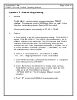
2.5 Remote Programming Connections (pin 6, 7 and pin 9).
The DX602 can be remotely programmed via a RS232C interface.
Data rate is 9600 baud, 8 bits, no parity, ASCII encoded per protocol
described in Appendix A.


