Avalon Instruments M-Uno User Manual Download Page 8

Moreover, considering that at the meridian the sky is less subject to light pollution and to 
atmospheric turbulence, the M-uno is the ideal tool to shoot deepsky objects in their best 
conditions, close to the meridian, especially when the time is short and the sky is not so dark and
clear.

The M-uno is mainly designed for astroimaging with high focal length catadioptric tubes (such 
as SC-Maksutov, RC, SC cameras, Cassegrain, DK, etc) up to 10″ aperture and 20 kg (44 lb) 
weight, according to the tube length. It is possible to use the M-uno with Newton optics (for 
example 8" f4) and even with short refractors (400-500 mm), with a piggyback or parallel 
guidescope.

To allow the use of refractors with length exceeding approximately 500 mm, an optional 
accessory has been realized allowing to distance the telescope from the mounting flange in order
to allow the passage over the RA axis. It is also available a special kit that, in addition to 
distance the telescope from the mount, allows the housing of a small guide-scope obtaining also 
a better telescope balancing. With this configuration it could be necessary to perform the 
telescope inversion at the meridian passage in the case of the telescope striking the tripod.

However  the  larger overhang of  the single arm  system will  allow a greater  pointing angle
compared to the classic German Equatorial Mounts.

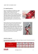
Another M-uno basic advantage is that it doesn't need neither counterweights, nor the bar. Its 
declination axis can be quickly balanced like in an equatorial mount, while, for the RA axis, it is
possible to fix the arm on three possible positions and to make the fine balance using a very 
small counterweight. The M-uno mount, as well as the LINEAR, is equipped with the super 
tested, simple to use and inexpensive Synscan control system. The M-uno total weight is only 
14.9 kg (11 lb) and it is provided of a confortable handle for easy transportation. With these 
features, in terms of lightness and transportability, the M-uno ranks at the top of the mounts with
capacity up to 20 kg (44 lb).

The use of pulleys and toothed belts has allowed to obtain several advantages: a really steady 
motion without play (no backlash) and sudden peaks, factors of paramount relevance for long 
guided exposures and during high magnification visual observations. These features are of 
particular relevance especially for the declination axis motor that can now quickly reverse the 
motion without breaks to recover the plays: from here the mount name FAST REVERSE. The 
toothed belts used in the M-uno have the structure made of special material with steel strands to 
avoid any deformation, elongation and stress, much better than those used in the automotive 
engine distribution system (which are generally made of rubber with nylon strands). 
Considering that the service time for the automotive toothed belts is around 100.000 km (60.000
miles), assuming a medium regime of 2.000 rpm and thermal stress from 0 to 90°C (30 to 195 F)
in a few minutes, we can think that the life cycle of the M-uno toothed belts will be extremely 
long ! It is important to underline that in the gear-worm systems the motion transmission has 
only one tangent point of contact, any errors on each of the two components will, sooner or 
later, result into a tracking errors. On the contrary, in the pulley-toothed belt system, no direct 
contact occurs between the pulley and the motion is transmitted by the belt engaging from 50% 

© 

All Rights reserved

 - 

8

Summary of Contents for M-Uno

Page 1: ...ANUAL Version 2 0 1 July 2020 All the pictures and contents included here are propriety of AVALON INSTRUMENTS They cannot be reproduced published copied or transmitted in any way including the interne...

Page 2: ...be used exclusively by adults do not allow use to children or to people with reduced mental capacity Avoid to operate the mount except as strictly indicated in the manual Modifying or altering in any...

Page 3: ...scope installation 17 4 Telescope Balancing 19 4 1 Dec Balancing 19 4 2 RA Balancing 20 5 M uno mount stationing 22 5 1 Latitude Fine Adjustment 22 5 2 Azimuth Regulation 23 5 3 M Uno Polar Alignment...

Page 4: ...minum with high precision CNC machines Transmission System Pulleys made with special polymer fiber glass and high quality toothed belts RA Axis Heavy duty steel diam 35mm all roller bearing axis movem...

Page 5: ...or the use with third party software and in particular with the ASCOM driver are reported in the StarGO manual which is part of the mount supply A careful reading of this manual will enable the use of...

Page 6: ...ower supply with related cable StarGO control Keypad Keypad connection cable Metric Hexagonal key set Mount Transport Handle Mount head with tripod plate and dovetail platform including the StarGO con...

Page 7: ...aided design CAD High quality manufacturing with digital control 5 axes CNC machines CNC CAM Absolute quality materials Anodized aluminium from milled mono bloc stainless steel components and screws b...

Page 8: ...nce using a very small counterweight The M uno mount as well as the LINEAR is equipped with the super tested simple to use and inexpensive Synscan control system The M uno total weight is only 14 9 kg...

Page 9: ...tor slipping during GOTO operation is virtually null On the contrary it is well known the difficulty to regulate the coupling between gear and worm in the conventional mounts If the coupling is tight...

Page 10: ...il the procedures to set the correct range of latitudes of the site where the mount will be used The latitude range setting must be performed before installing the mount on the tripod As said the M un...

Page 11: ...rews 1 and 2 under the base Remove the screws numbered 1 2 3 and 4 from the side plate Remove the plate to expose the brass plug Remove the two screws from the brass latitude adjustment plug All Right...

Page 12: ...the two screws previously removed from under the mount 3 2 Installing the M Uno on the Tripod Whatever type of tripod is used it must be mounted with the right orientation This need that the brass con...

Page 13: ...that purpose The following are the steps necessary to install the M Uno mount on a T Pod tripod Unscrew the azimuth adjustment knobs a few turns by rotating the azimuth adjustment knobs in opposite d...

Page 14: ...g refractors may require the use of the optional extension cylinder which could also block the polar alignment scope An easy solution to this problem is achieved with an optional accessory to enable m...

Page 15: ...de closer to the ground goes in first as shown in the picture While holding the telescope with one hand use your other hand to rotate the knob on the dovetail saddle clamp as shown in the right pictur...

Page 16: ...ces strain on the motors With the M uno mount it is better to start balancing the DEC axis rather than the RA axis The M uno is unique in that it allows the RA axis to be almost automatically balanced...

Page 17: ...uin your entire day 4 2 RA Balancing Balancing the M uno mount in the Right Ascension axis is different from the other German Equatorial Mounts but it is quite easy to do The balance is performed in t...

Page 18: ...uitable for many catadioptric OTAs Warning do not use different screws other than those supplied or serious damage to the gear system may occur Precise balancing Once the mount arm has been set in the...

Page 19: ...ss consists of approximately setting the polar axis at an angle equivalent to the latitude of the observation site For example Rome is about 42 North Milan and Venice 45 North and Palermo 38 North Ref...

Page 20: ...Latitude and Azimuth should be performed only during the important phase of precise polar alignment before starting an observation or photographic session Once the polar alignment has been reached THE...

Page 21: ...kit Beginning in 2016 the Skywatcher polar scope included with the mounts have a different reticle view than earlier models However the Polar Alignemnt procedure with the M Uno mount remains the same...

Page 22: ...esents the position of the Polaris The problem here is to turn the reticle around the small cross in the centre to put the small circle in the position where the Polaris is seen from a given observati...

Page 23: ...movement respect to the tripod In case of use of the new reticle on the right figure the only difference is that the operation number 2 is not more necessary The position of the Polaris on the circle...

Page 24: ...m are based on a similar concept A virtual reticule often representing the real reticule present in the Polarscopes with the position of the Polaris in function of the observation site coordinates the...

Page 25: ...t matter how the reticle is rotated If Polaris is in the same position on the orbit indicated by the chosen Polar Finder app an accurate Polar Alignment has been accomplished As it appears in the app...

Page 26: ...line in the reticle with the slot for the Polaris indicated in the reticle is oriented at the same angle by the chosen smartphone or tablet application 2 Make very small movements of the azimuth and...

Page 27: ...ed software requiring therefore a Windows or Mac PC that however should be available for the successive astrophotography session That CCD must be firmly installed on the mount keeping a good paralleli...

Page 28: ...correct pressure This adjustment it is performed from the factory So in case the mount will be disassembled from its base it must be reassembled taking care to adjust the three knobs with the same pre...

Page 29: ...ia AUX1 and AUX2 port The AUX1 and AUX2 port control on the StarGo GUI can be found on the AUX panel as described at page 30 of the StarGo User Manual By clicking on this tab the ports settings will s...

Page 30: ...To enable this software version it must be checked the AUX as Motorized Polar Alignment option in the AUX tab as shown in the picture below This tool allow to move the selected motor with the ArcMin...

Reviews: