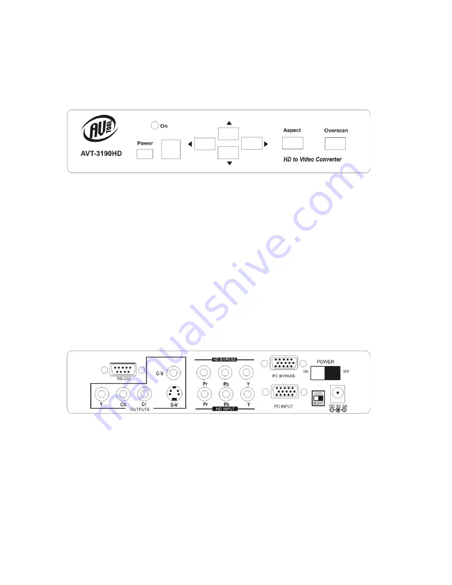
4.0 CONNECTING THE HARDWARE
Please study the drawings below and become familiar with the inputs, outputs
and control locations on the AVT-3190HD.
AVT-3190HD Front Panel
The Power Button switches between “Standby” and “On”. When the unit is turned
on, the LED marked “On” above and slightly to the right of the power switch will
illuminate.
The Square window area to the right of the power switch is the location of the
Infrared sensor used by the remote to control the unit. It must remain unblocked
if the Remote IR unit is used to control the unit.
The Four buttons with the arrows are used to position and pan the image. The
Aspect button allows switching between wide screen and standard display
modes and the Overscan button allows magnification of the image.
AVT-3190HD Rear Panel
The inputs and outputs on the rear panel are clearly marked. Connect the
appropriate cables to the inputs making certain that the cables are in good
condition and undamaged. The power switch (Upper right on the drawing above)
removes or applies power to the unit. If the switch is in “Off” position, the power
switch on the front will have no effect since it is a Standby switch, not an actual
power switch. The Switch next to the power connector is used to switch between
PC input and HDTV input.
8


