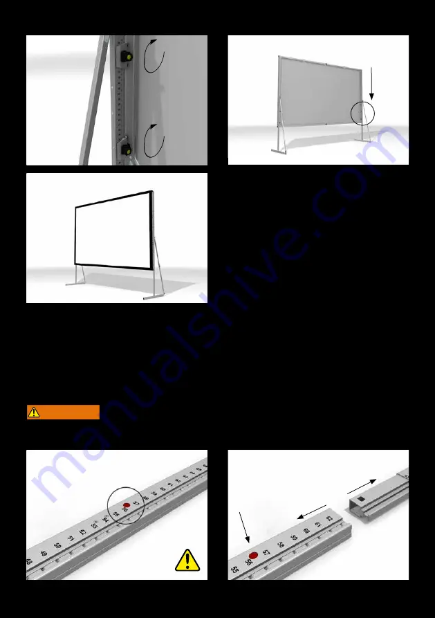
21
5
6
DISASSAMBLY
1-2
To disassemble the leg components, push the red button to loosen the snap joint.
WARNING
Danger of injury due to improper disassembly.
Falling parts can cause severe injury or death!
Page 1: ...28HS AT64 SHIFT INSTRUCTION...
Page 2: ...patented snap joint technology Special extruded and hardened aluminum alloy allows maximum stability at minimum weight FRAME ADAPTERS Frame adapters and accessories in yellow bag LOCKING AND SLIDING...
Page 3: ...torage bag for projection screen SOFTBAG WITH WHEELS padded tearproof nylonbag with wheels and carrying straps small 128x25x30 cm big 133x31x35 cm AT64 SHIFT BASE MODULE 26 67 cm ASSEMBLY INSTRUCTION...
Page 4: ...VICE 8 WARRANTY 9 AT64 SHIFT 10 LEG HEIGHTS 11 FRAME SETUP 12 ADAPTERS 13 LEG LENGTH ADAPTER POSITIONING 13 LOCKING SLIDING MODULES 14 UNLOCK 15 LEG ASSEMBLY 15 16 RELOCK 17 SURFACE MOUNTING 17 RAISIN...
Page 5: ...e labels on each component and on the labeled soft bags roller bags or flight cases SAFETY GENERAL INFORMATION FOR THE MANUAL AND SAFETY This operating manual forms part of the projection screen syste...
Page 6: ...he instructions in chapter LEG HEIGHTS site 11 Prevent air draft Use additional weights on the base profile of the leg to gain higher stability Use suspension points e g EasyFly according to the overa...
Page 7: ...en then all plug in and clamp connections must be secured against becoming loose and falling It is not allowed to use the projection surface holding the frame parts in position Falling parts can cause...
Page 8: ...ront layer inside in order to avoid soiling and damage When folding the projection surface insert the enclosed foamed plastic foil between snap buttons and surface to avoid permanent marks COLD BREAK...
Page 9: ...y with the local safety regulations Inappropriate use misuse Use of unauthorized and non trained staff Unauthorized equipment conversions and technical modifications by the operator himself Use of spa...
Page 10: ...ENERAL PRODUCT FEATURES easy height adjustment in assembled condition tool free automatic securing of the height adjustment 8 different lengths possible compatible with all mobile AV Stumpfl screen sy...
Page 11: ...Leg supports have a telescopic element that is thigtend with two wing screws base module 4x42 107cm 1x21 53cm base module 4x42 107cm base module 3x42 107cm 1x21 53cm base module 3x42 107cm base module...
Page 12: ...ed either with a red or green square which indicate the corresponding side of the frame 4 5 For easy mounting by a single person we recommend making use of the leg set up support Lift the screen and s...
Page 13: ...es 2 Depending on screen height desired setup height and leg length choose the best position to attach the adapters for the sliding modules 3 5 Attach the frame adapters to the round spacers on the ba...
Page 14: ...les to the lower two adapters of the frame 2 5 Secure the bayonet coupling by turning the module into the aligned direction with the frame and make sure that the colored squares facing to the outside...
Page 15: ...the two locking mechanisms Just pull the button and turn it counterclockwise LEG ASSEMBLY 1 2 Assemble the numbered extension parts Just plug together the components The snap lock will engage automat...
Page 16: ...g in profile protrudes from the bottom frame corner 5 7 Assemble the next extension part s with the end module and connect them 8 9 Now put on the base module and shift the complete leg until the vert...
Page 17: ...CK 1 3 Finally secure the two locking mechanisms and continue with attaching the opposite leg Repeat all the steps for the other side SURFACE MOUNTING 1 3 Remove all leg set up supports and attach the...
Page 18: ...to ambient conditions and particular stability needs 1 3 Bolt the support to the leg by the enclosed wing screw and secure the telescopic part with the two wing screws RAISING UP 1 3 Since the projec...
Page 19: ...he screen up to your preferred position The AT64 SHIFT will lock automatically 4 Two locking modules on each side make the screen system leg even more robust and safe to use 5 The height can be adjust...
Page 20: ...safety catch HEIGHTADJUSTMENT DOWN To move the frame further down just use the locking mechanism 1 Loosen the upper locking module 2 3 Safeguard the screen frame manually and unlock the lower module...
Page 21: ...1 5 6 DISASSAMBLY 1 2 To disassemble the leg components push the red button to loosen the snap joint WARNING Danger of injury due to improper disassembly Falling parts can cause severe injury or death...
Page 22: ...22 AV Stumpfl GmbH Mitterweg 46 4702 Wallern AVstumpfl AVstumpfl com www AVstumpfl com 43 7249 42811...