AV Link SX-2044 User Manual Download Page 9

SX Matrix Switching System

User Manual 


8

5.0 SX Matrix System and Peripherals Connection 


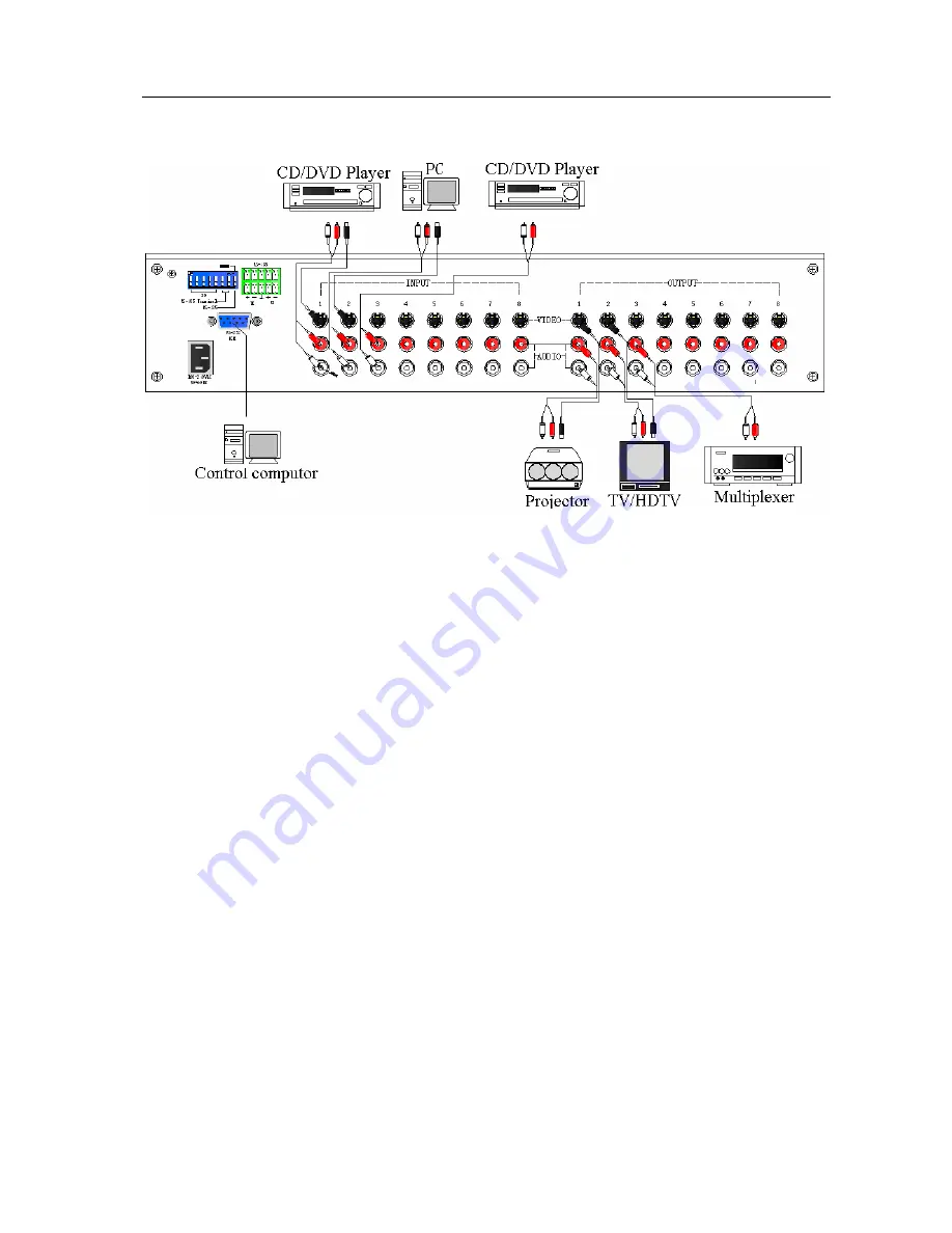
Figure 5-1 SX Matrix System Connection 


5.0.1 Input/Output Jacks 

Referring to the different models, the video signal input/output jacks are formed by the 4th 

row and 8th row S-Video and RCA female terminals. Lining from the top to the bottom are 

respectively video and audio signal terminals. The video signal terminals are S-Video, the audio 

signal terminals are red (right audio channel) and white (left audio channel). Channels of the 

output terminals are numbered from left to right from 1 to 8. Refer to the drawing on the housing 

for port terminals of different models. 

Different models of the SX matrix system provides a different number of input/output jacks 

for users to connect to different audio/visual equipment including CD/DVD players, graphics 

workstations, and number displays. The output terminals can be connected to projectors, video 

recorders, displays and multiplexers and so on. 


5.0.1.1 Audio Connecting Cable 

Different models of the SX matrix system provides a different number of input/output jacks 

for users to connect to different audio/visual equipment including CD/DVD players, graphics 

workstations, and number displays. The output terminals can be connected to projectors, video 

recorders, displays and multiplexers and so on. 

S-Video video connector is a standard (Y/C

Min-din 4PIN connector. 

RCA audio connector is a pair of (R/L) female RCA connectors. 

The SX Matrix supports various AV signal sources. 

Summary of Contents for SX-2044

Page 1: ...User Manual SX 2044 SX 2084 SX 2088 SX Series Matrix Switching Systems...

Page 2: ...be installed indoor only Install either on a sturdy rack or desk in a well ventilated place 3 Lightning Unplug the power cord during lightning or after a prolonged period of non use to avoid damage t...

Page 3: ...munication Port 12 5 0 3 3 On Off Switch Settings 13 5 0 3 4 SX Matrix System and Control System Connection 15 6 0 Matrix System Control Panel Operation 17 6 0 1 Input Output Switching Key Operating M...

Page 4: ...SX Matrix Switching System User Manual 3 9 0 SX Matrix System Technical Parameters 29 10 0 Common Problems and Solutions 30...

Page 5: ...tion and high fidelity graphics and audio signal output The SX Matrix is used mainly in TV broadcasting projects multi media conference halls large display projects TV teaching and command control cen...

Page 6: ...anual 2 0 SX Matrix Host Installation The SX Series Matrix Host has a black metallic housing It can be placed on a sturdy desk or installed on a 19 in rack See Figure 2 1 below Figure 2 1 Installing t...

Page 7: ...nts of different users Technical Parameters Model Video Input Port Video Output Port Audio Input Port Audio Output Port RS 485 Connector RS 232 Connector SX 2044 4 4 4 4 SX 2084 8 4 8 4 SX 2088 8 8 8...

Page 8: ...ng System User Manual 7 4 0 2 SX 2084 Front and Rear Panels Figure 4 3 SX 2084 Front Panel Figure 4 4 SX 2084 Rear Panel 4 0 3 SX 3088 Front and Rear Panels Figure 4 5 SX 2088 Front Panel Figure 4 6 S...

Page 9: ...odels Different models of the SX matrix system provides a different number of input output jacks for users to connect to different audio visual equipment including CD DVD players graphics workstations...

Page 10: ...video interference Presently almost every TV set provides this connector for video input Connection method Use the RCA type socket for connection Connect the video S Video and audio RCA R L connector...

Page 11: ...5 0 3 Remote Control and Settings The SX matrix provides standard RS 232 and RS 485 serial communication ports Aside from using the front panel keys for switching operation you are also permitted to u...

Page 12: ...SX Matrix Switching System User Manual 11 Figure 5 5 Figure 5 5 a...

Page 13: ...User Manual 12 Figure 5 6 Note The Matrix RS 232 port is defined as DCE 5 0 3 2 RS 485 Communication Port You can use the RS 485 port to control more than one SX product The RS 485 Port as shown in F...

Page 14: ...6 7 RS 485 Terminator ON OFF ON Terminator ON OFF Terminator OFF C DIP sw 1 to 5 Setting address setting The ID address determines the position of a SX Matrix system When multiple SX products are conn...

Page 15: ...OFF ON OFF ON OFF 11 0B 01011 OFF ON OFF ON ON 12 0C 01100 OFF ON ON OFF OFF 13 0D 01101 OFF ON ON OFF ON 14 0E 01110 OFF ON ON ON OFF 15 0F 01111 OFF ON ON ON ON 16 10 10000 ON OFF OFF OFF OFF 17 11...

Page 16: ...in Figure 5 9 below Figure 5 9 NOTE 1 RS 232 connection refer to previous Figure for operation 2 RS 232 or RS 485 baud rates 9600bps no odd or even calibration address 8bit data transmission address...

Page 17: ...85 baud rate 9600bps no odd or even calibration address 8bit data transmission address 1bit stop address 96 N 8 1 2 Connect your PC RS 485 port to the Matrix RS 485 port as follows TX TX TX TX RX RX R...

Page 18: ...to 8 for connection to peripheral display equipment Input Channel The IN Row 1 8 keys on the front panel represent input channels 1 to 8 for connection to the currently connected channels of the sign...

Page 19: ...hannel key to retrieve the saved input output status and implement this status switching 8 AUDIO The audio switching selection key switches to another output channel from the same channel Example Pres...

Page 20: ...ss the NO 1 key of the Input channel for 2 seconds for selection of NO 1 channel to input into NO 3 channel for output The LCD shows 1 at channel NO 3 for both Audio and Video Enter the Output channel...

Page 21: ...nnel and output from NO 1 channel Enter the output channel when VIDEO shows 4 at NO 1 channel on LCD 4 Press the NO 3 key of the output channel for 2 seconds and enter the input channel when the red 0...

Page 22: ...y of the input channel for 2 seconds to select the operation of input from NO 4 channel and output from NO 1 3 5 and 6 channels VIDEO shows 4 at NO 1 3 5 and 6 channels on LCD 7 0 Matrix Application S...

Page 23: ...rol Computer Connection Turn on power to the SX matrix and the computer Activate the AV Matrix exe on the bundled CD ROM in the control computer to enter the control software interface 7 0 2 Software...

Page 24: ...number key 01 to the bottom Afterwards press consecutively the previously selected Output number keys 02 03 and 05 or you can press the Deselect all output key This way you have selected Input 01 and...

Page 25: ...t and input number key 01to the bottom Afterwards press consecutively the previously pressed output number keys 01 06 and 07 to the right or you can press the Deselect all output key This way you have...

Page 26: ...he present input and output relations are shown in Figure 7 2 below 7 2 Now you have to close the output ports 03 05 and 06 Step 1 First press down the output number keys 03 05 and 06 to the right Ste...

Page 27: ...nected to the equipment The needed input output ports should be set to audio video channel 1 while switching all output ports to output Make sure you have selected both Video and Audio by checking the...

Page 28: ...sent input output switching relations to Location 1 Retrieve Function Description To retrieve the saved input output switching relations A specific example of the Retrieve Function is described below...

Page 29: ...Applications Displays the presently saved switching status as shown in Figure 7 5 below Figure 7 5 When Video Audio corresponding to Output is open it shows the Output ports corresponds to the Video...

Page 30: ...ors 8 S Video Female Connectors 4 S Video Female Connectors 4 S Video Female Connectors Min Max Voltage 2 5Vp p Impedance 75 Audio Signal Input Output Connectors RCA R L Female Connector Signal Type S...

Page 31: ...ideo signals output to display Answer Ghosting is often caused either by the projector inferior cable quality or long transmission distance You are advised to adjust the projector or replace with bett...

Page 32: ...n Simply replace the connectors 2 It could be the connection cable short circuited Simply replace the cable 3 It could be the connection cable is broken Simply replace the cable 10 What to do if the S...

Reviews: