

VERSION 1.9
J120 (38198-X)
J120 Rev 1 (38198)
First revision of the J120. Very limited distribution.
J120 Rev 2 (38198-2)
Second revision of the J120. It became available in late April 2016. Modifications:
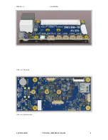
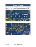
• all 3 connectors on the left are aligned (Ethernet, USB3 and mini HDMI)
• PCB size: 50 x 109.5 mm, total size: 50 x 110 mm
• M.2 type M fixed
• auto start recovery time shortened
• optional super cap for RTC
• firmware upgrade (back powering fix)
• INT lines of CAN controllers connect to individual pins of the TX1 (interrupts not shared)
J120 Rev 3 (38198-3)
• fixed USB2 power (flash recovery now supported)
• optional resistor to combine power to the 2 USB 3 ports
• added UART2 RXD/TXD to J7 (with components changes it could be reverted back to UART0 RTS/CTS)
• replaced 12V power in diodes with MOSFETs (for controlled inrush ramp up with Lipo batteries)
• four TX1 mount holes now connected to GND
• added LM75 temp sensor
• only one CAN bus and connector (CAN2) to overcome problem with SPI1_CS0 line - one CAN bus
supported with TX1 firmware provided by Auvidea
J120 Rev 4 (38198-4)
• changed I2C pullup resistors from 1k to 10k (to improve I2C signal low level)
J120 Rev 5 (38198-5)
• I2S connector: changed from I2S2 to I2S0 (for additional GPIOs)
• optional: 2 CAN busses (requires SW fix for SPI1_CS0)
• M.3 spacer to fix M.2 2280 SSD card
• bottom USB3 connector may be configured to carry SATA signals (optional)
J120 Rev 6 (38198-6)
• added MCU (STM32F042) for watchdog option - this MCU tunnels the UART0 port of the TX1 and TX2
• initial revs of the MCU firmware only support 38400 baud
• added INA3221 power monitor chip (12V, 5V, 3.3V) - this chip is not populated on the base version
J120 Rev 7 (38198-7)
• RN45 populated to bring out UART2 on connector J7
AUVIDEA GMBH
TECHNICAL REFERENCE MANUAL
5