background image


1.  RCA Line Output Jacks 

Full range output from channel L + R inputs is provided at Line Out Jacks 

2.  RCA Low Level Input Jacks 

It allows left and right inputs to be connected to the amplifier using RCA plugs. 

3.  Input Level Control 

It allows for the adjustment of the gain of both channels to match the output level of the source. 

4.  High Variable Controls  

Adjust the crossover frequency of the High Pass output only, from 75Hz to 750Hz. 

5.  Low Variable Controls  

Adjust the crossover frequency of the LOW pass output only, from 40Hz to 150Hz. 

6.  Bass Boost Controls  

Adjust the sub boost level of the selected frequency output from 0dB to + 18dB. 

7.  X-over switch 

a)  Low position: Allows for the control of the low pass frequency range (40Hz-150Hz) by 

using the Low Variable. 

b)  Flat position: Allows for full range pass through. 
c)  High position: Allows for the control of the high pass frequency range (75Hz-750Hz) by 

using the High Variable. 

8.  Subsonic Filter 

It allows to delete the frequency under 35Hz for Subwoofer protection. 

9.  Power & Protection indicator 

It has two color indicator and the Green indicator indicates amplifier has turn on signal. The Red 
indicator indicates the fault operation of the amplifier. When the fault conditions (overload, 
excessive heat or short circuit of speaker) arise, the protection circuit is engaged to protect both 
the speakers and amplifier against damage. 

10.  Fuse 

It protects both the amplifier and automobile electrical system from fault conditions. Use a 
standard automotive fuse, 300.S:30A, 400.S:40A, 500.S:40Ax2. 

11.  Power connection 

Co12VDC power wire from the battery and also connects ground wire from a suitable 
ground point on the chassis. 

12.  Remote connection 

Connects the control wire which allows the amplifier to be turned on and off by the radio cassette 
player. 

13.  Speaker Terminal 

It allows the connection of speakers to the amplifier. 

Summary of Contents for 300. S

Page 1: ...2Channel Musical High Performance Flush Mount Amplifier MODEL 300 S 400 S 500 S Owner s Manual Owner s Manual...

Page 2: ...fecting your sensitive hearing Sound can be deceiving Over time your hearing comfort level adapts to higher volumes of sound what may have sounded normal can actually be too loud and harmful to your h...

Page 3: ...urface preventing air circulation Mark the location fro the mounting screw holes by using the amplifier as a template Drill 29 or 9 64 diameter holes at the marked locations and firmly fasten the ampl...

Page 4: ...using spade lug with insulating sleeve This wire is the electrical ground and must be fastened securely to the vehicle chassis The best method is to use a shelf threading sheet metal screw since the t...

Page 5: ...ferent type or rating may result in a serious hazard This amplifier has two types of signal input terminal RCA connector for low input Adjustment of input levels is accomplished by the gain control of...

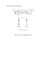
Page 6: ...SIGNAL INPUT CONNECTIONS Fig 3 Signal Input Connections Note RCA Cable not supplied with unit...

Page 7: ...to phase the speakers Improper phasing causes a loss of bass response When used in the BRIDGED mode the speaker wires should be connected to the output terminals of the amplifier as shown Ref To Fig...

Page 8: ...FEATURES AND CONTROLS Fig 5 Features and Controls...

Page 9: ...or the control of the high pass frequency range 75Hz 750Hz by using the High Variable 8 Subsonic Filter It allows to delete the frequency under 35Hz for Subwoofer protection 9 Power Protection indicat...

Page 10: ...r Separate High Pass 75Hz 750Hz Variable Low Pass 40Hz 150Hz Variable Slope 0 12db OCTAVE Subsonic Filter 35Hz 3dB Bass Boost 0 18dB Variable Input Sensitivity 200mV 4Volts Variable Input Impedance Lo...

Page 11: ...el Example 30 Quiet library soft whispers 40 Living room refrigerator bedroom away from traffic 50 Light traffic normal conversation quiet office 60 Air conditioner at 20 feet sewing machine 70 Vacuum...

Reviews: