Autoquad ESC32 2r1 User Manual Download Page 4

Page:4

ESC32 2r1 user manual - version 0.0
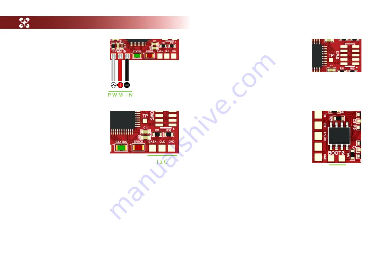
1.4 PWM connection

Solder the PWM servo wire to the 

PWM pads or add header pins. 

1.5  I2C connection

The ESC32 offers a I2C bus connection 

for  future  use.  Support  for  MK  I2C 

control  will  be  released  as  soon  as 

we  had  a  chance  to  test  it  properly  - 

talented people are working on this - a 

beta release is expected soon!

1.6 CAN-connection (Optional)

ESC32 can be fitted with an optional CAN transceiver (Texas Instruments 

SNHVD232) to provide CAN-bus control and bidirectional communication at 

up to 1Mbit/s. Currently CAN is not supported in the Firmware. It is also a 

work in progress, and we will release a driver for it when we had more time 

to implement and test CAN control. 

1.7 Cortex SWD connection. (J4)

A standard 10-pin SMT Cortex (TM) SWD connector 

(Samtec FTSH-105-01-F-DV) can be soldered to the 

board for realtime debugging of ESC32. 

1.8 Boot jumper

The  boot  jumper  is  used  to  place  the  STM32 

bootloader  in  flash  mode  for  uploading  new 

firmware.  Short  these  two  pads  during  power-up 

to activate the Bootloader and place ESC32 in flash 

mode (Hint: you can use a pair of tweezers, if you 

are  bit  handy  -  you  don´t  need  to  keep  the  pads 

shortened after the ESC has been powered up)

Summary of Contents for ESC32 2r1

Page 1: ...port onboard Firmware written completely in C Cortex SWD connector pads for real time debugging Communications ports PWM IN UART I2C CAN Bus Communications protocols PWM IN CLI binary 1 wire I2C CAN 4...

Page 2: ...nd the limiting factor is simply cooling If you can get them into some prop wash or rig some sort of small heat sink your results will get better I ve been flying them for for more than 6 months with...

Page 3: ...input capacitor polarity The MINUS mark on the capacitor must be connected to the terminal of the ESC32 Failing this can blow up the capacitor and damage the ESC32 Make sure the capacitor legs are kep...

Page 4: ...nal communication at up to 1Mbit s Currently CAN is not supported in the Firmware It is also a work in progress and we will release a driver for it when we had more time to implement and test CAN cont...

Page 5: ...ce either from an external regulator or a UBEC hooked up to the servo rail on your FC or receiver Selecting 5V also means you can power up the logic side separately when flashing firmware or altering...

Page 6: ...urce ESC32 is now ready to run as a standard PWM ESC with a very high motor refresh rate and a 1000 1950us throttle range with the motor start at 1100us As such it can now be mounted to your favorite...

Page 7: ...enu Then go to the tab ESC32 settings On the left side of the screen you can see the Link ESC32 Tab Connect UART adapter to ESC32 and computer and choose the UART adapter you are using and click conne...

Page 8: ...unless you are know how the different parameters affects opera tion Certain parameter combinations can be fatal for the ESC and motor Refer to the User configurable parameters section for more informa...

Page 9: ...t yet implemented BAUD_RATE 230400 The UART baud rate Allowable range 9600 to 921600 PTERM 0 5 The P term for the RPM PI controller ITERM 0 0006 The I term for the RPM PI controller FF1TERM 0 0 Feed f...

Page 10: ..._CURRENT 20 The maximum amount of current in amps that the ESC will allow Current is dynamically regulated Al ways set this value low and only increase it if you know what you are doing SWITCH_FREQ 20...

Page 11: ...requires calibration of the specific motor and prop you will be using The calibration sequence is not yet supported in QGC but can be run under Linux and OSX from a terminal Closed loop calibration is...

Reviews: