-|Transparent Guide|-
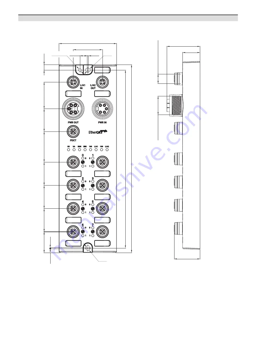
Dimensions
•
Unit: mm, For the detailed dimensions of the product, follow the Autonics website.
4.7
1.3
6.3
215
8.35
33.4
24
26.5
35
26
30.5
Ø4.5
M4 X 0.7
66
203.35
20
38
29.6
M12 X 1 ( X 11EA)
7/8 " ( X 2EA)
Page 1: ...fy the unit Failure to follow this instruction may result in fire 06 Do not touch the product during operation or for a certain period of time after stopping Failure to follow this instruction may result in burn Caution Failure to follow instructions may result in injury or product damage 01 Use the unit within the rated specifications Failure to follow this instruction may result in fire or short...
Page 2: ...from the Autonics website IO Linkdevice ADIO EC IO LinkMaster EtherCATMaster Configurationtools ESIfile IODDfile Powersupply Operation mode Safe State01 Vali dation Data Storage Input Filter 01 Vendor ID Device ID Cycle Time Digital Input Digital Output IO Link Input IO Link Output IO Link Input Output 01 Unsupported on the atIOLink The supported objects ProductComponents Product 1 Name plates 20 ...
Page 3: ...ide Dimensions Unit mm For the detailed dimensions of the product follow the Autonics website 4 7 1 3 6 3 215 1 3 8 35 33 4 24 26 5 26 5 26 5 35 26 30 5 Ø4 5 M4 X 0 7 Ø4 5 66 203 35 20 38 29 6 M12 X 1 X 11EA 7 8 X 2EA ...
Page 4: ...Mounting 01 Prepare a flat or metal panel in the enclosure 02 Drill a hole to mount and ground the product on the surface 03 Turn off all power 04 Fix the product using M4 screws in the mounting holes Tightening torque 1 5 N m M4 M4 Installation UnitDescriptions 1 2 3 2 4 4 5 5 6 7 8 9 04 Ethernet port 05 Power supply port 06 PDCT port 07 I O port 08 Status indicator 09 I O port indicator 01 Groun...
Page 5: ...nector 1 Function Connector 2 Pin no Connector 2 Function 1 N C 1 5 VDCᜡ 2 Data 2 Data 3 0 V 4 0 V 4 N C 5 Data 3 Data 01 Connect to the EtherCAT 01 Connect the M12 connector to the Ethernet port See the connections below 1 2 3 4 1 TX Transmit Data 2 RX Receive Data 3 TX Transmit Data 4 RX Receive Data 02 Connect the connector to the EtherCAT network Network device PLC or EtherCAT device supportin...
Page 6: ...twork device Network device PC laptop that atIOLink software is installed 03 Put the waterproof cover on the unused port PortConnections 04 Connect the power supply to ADIO Be sure not to exceed 9 A of the maximum supplying current to the sensor US 01 Turn off all power 02 Connect the 7 8 connector to the power supply port See the connections below 1 2 0 V Sensor and actuator supply 3 F G Frame gr...
Page 7: ... Description ERR Red OFF No error Flashing Invalid configuration Flashing once Local error ON Error in application 06 Ethernet connection Indicator LED Color Status Description L A1 L A2 Green OFF No Ethernet connection ON The Ethernet connection is established 07 Transmission rate of the Ethernet Indicator LED Color Status Description 100 Green ON Transmission rate 100 Mbps I O port indicator 01 ...
Page 8: ...nt Voltage 15 VDCᜡ Current 2 mA OFF voltage 5 VDCᜡ Environmental conditions Ambient temperature01 5 to 70 C Storage 25 to 70 C no freezing or condensation Ambient humidity 35 to 75 RH no freezing or condensation Protection rating IP67 IEC standard IP69K DIN standard 01 UL approved ambient temperature 45 Approvals Approval ᜢ ᜨ ᜣ Association approval ᜬ Electrical Mechanical specifications Supply vol...