Automation Direct FPM-150 User Manual Download Page 7

 
Using the Auto-Adjust


The FPM-150(-TS) will attempt to adjust itself to your computers current video model. If 
the picture is stable, and centered vertically and horizontally the automatic adjustment is 
complete. If however the picture is not stable, and centered vertically and horizontally 
you can re-initate the auto-adjustment.  Once you have the unit displaying the resolution 
you desire for your application do the following: 

Press and release the “Select” button on the membrane. This will place the unit into a 
“Geometry Auto Adjust” mode. This operation will adjust the picture so it is centered both 
vertically and horizontally on the LCD screen. It will also make the necessary 
adjustments to the internal clock timing so that the picture is stable (without any 
decernable pixel jitter). 

After having completed this step you may wish to adjust the color balance.  This 
procedure adjusts for any imbalance in the Red, Green, and Blue levels from the video 
cable or video card. This is accomplished using the LCDs OSD ( On Screen Menu) 
system.  

OSD (On Screen Display) Adjustments


There are four membrane buttons (see Fig 1, above) located on the rear of the unit. 
They will activate the OSD and allow navigation to all adjustments if your unit requires 
adjustment.


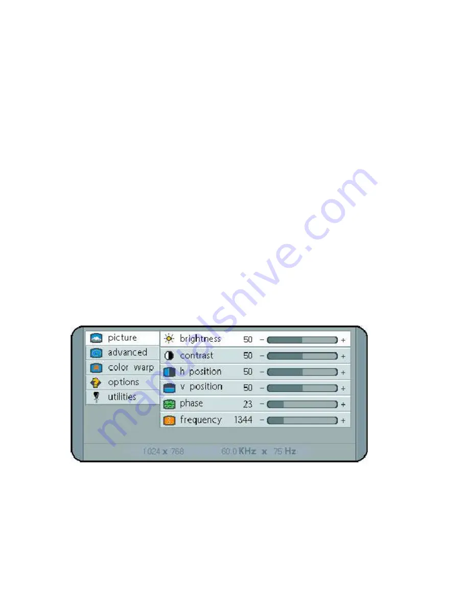
Press MENU key,OSD screen appears. [See Figure 2] 


Press UP/DOWN key, you can move between the five primary functions: 
Press Select key at Picture group to highlight this sub menu. You can now navigate the sub menu 
using the UP/DOWN keys. To make an adjustment to an item press Select and use the 
UP/DOWN buttons to make your adjustments 
 
At anytime, press the Menu button Two times to Exit and Save your settings. 
This convention of Menu, Navigate, Select Sub Menu, Navigate, Select Item and adjust is used 
throughout the OSD screen process. 
 

Summary of Contents for FPM-150

Page 1: ...FPM 150 FPM 150 TS LCD Monitor User Guide Revised 12 02...

Page 2: ...sting the Display Using the Auto Adjust OSD On Screen Display Adjustments Section 4 Touch Screen Set up Introduction to Touch Screens Touch Screen Driver Installation Windows 98 Windows NT 4 0 Windows...

Page 3: ...ilable on a VGA interface Today all of the above interfaces are available on a VGA interface but not all monitors support all resolutions The native resolution of the LCD is normally the maxium resolu...

Page 4: ...y near water Do not place any heavy objects on the power cords Damage may cause electrical shock Unplug the power supply from the wall or unit if one of the following conditions exists o Power cord or...

Page 5: ...ing system Note If for any reason the display goes blank and or displays out of Range or No Input Signal message on the screen your computer or video source may be putting out a signal that is incompa...

Page 6: ...standard on all models Adjusting the Display The FPM 150 TS Series display has an embedded microprocessor in the converter card this is the electronics that drives the LCD and has been recently update...

Page 7: ...er having completed this step you may wish to adjust the color balance This procedure adjusts for any imbalance in the Red Green and Blue levels from the video cable or video card This is accomplished...

Page 8: ...it Press the UP DOWN key you can now move between functions and press Select to adjust the value of each item with the UP DOWN key Press MENU key to return previous state and press MENU key twice to e...

Page 9: ...f screen can be activated with a gloved finger or mechanical stylus The touch screen itself is connected to electronics internal to the display unit that provide the Analog to Digital conversion When...

Page 10: ...om2 Remove the CD Restart the computer you will be prompted to calibrate the touch screen Touch each of the 3 targets as directed If the unit does not respond to your calibration touches then you have...

Page 11: ...prompted to calibrate the touch screen Touch each of the 3 targets as directed If the unit does not respond to your calibration touches then you have probably selected the wrong COM port If so press...

Page 12: ...ove the CD Select YES to Restart When the system restarts touch each of the 3 targets as directed If the unit does not respond to your calibration touches then you have probably selected the wrong COM...

Page 13: ...o continue Select Finish Remove the CD Select YES to Restart Go to the ELO icon under Windows Control Panel Verify the Com Port is correct Select Align then touch each of the 3 targets as directed If...

Page 14: ...h the power and video cables to the side of the monitor at this time 3 Install the monitor in the prepared cutout 4 Install the washers and lock nuts supplied with the monitor Note Use 10 32 nuts for...

Page 15: ...ccurs when a ghost of an image remains on the screen after the screen image has been changed Unlike a CRT monitor an LCD monitor s image persistence is not permanent To erase an image ghost turn the m...

Page 16: ...of range Use the on screen menu to adjust the Clock Setting Make sure timing is within VESA standard Slight distortion in text or Graphics Not working in native resolution Display is present but bars...

Page 17: ...ly to the cloth and not directly on the monitor screen Do not use paper products as they may scratch the surface To minimize the risk of abrasion allow the screen to air dry Special care should be tak...

Page 18: ...zontal Sync Pin 6 Red Video Ground Pin 14 Vertical Sync Pin 7 Green Video Ground Pin 15 Data Clock SCL Pin 8 Blue Video Ground Appendix B RS 232 Pin Assignments Pin assignment for 9 Pin Optional Touch...

Page 19: ...ew Angle L R 70 70 View Angle Up Dn 55 65 Input Voltage 90 264 VAC Auto switching Input power 25W Current Draw 20 120VAC Installed Depth 2 68 Chassis Construction 16 Ga SS Bezel Construction Al Machin...

Page 20: ...Appendix D Mounting Dimentions...

Page 21: ......

Page 22: ...NOTES Model Number _________________ Serial Number _________________...

Reviews: