background image

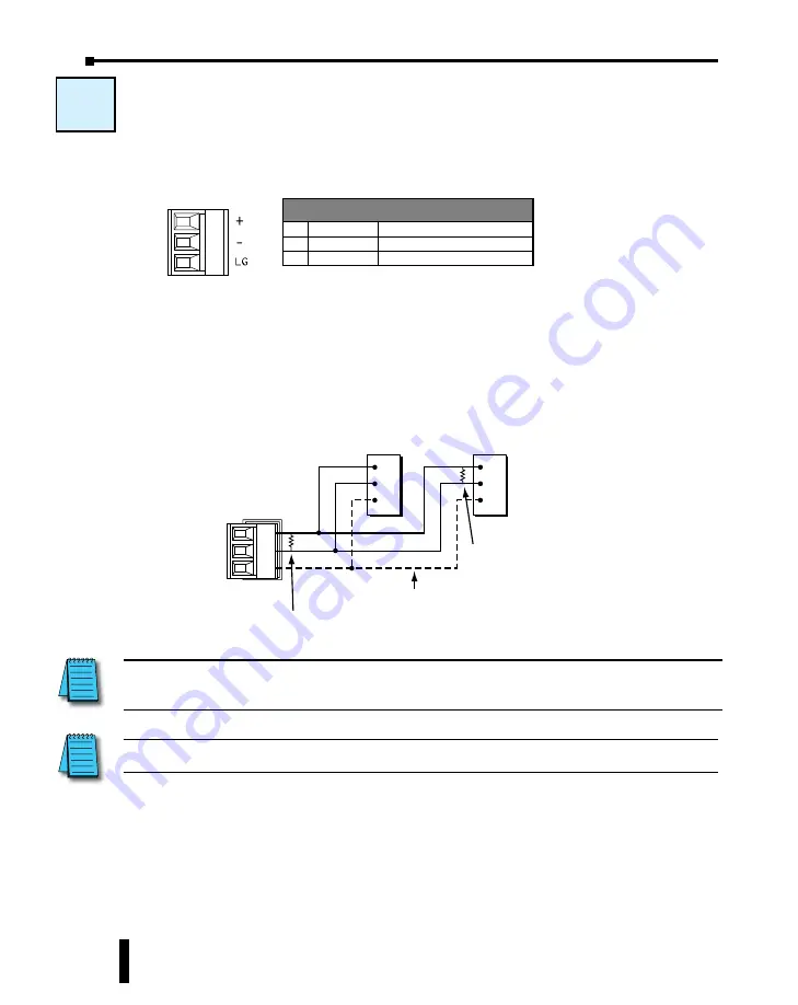
W-4: Com Port 3 Wiring

Com Port 3 supports 2-wire RS-485.

Wiring Strategy

You need to connect all + signal terminals in the network together.  You will also need to 

connect all – signal terminals together.  It is optional to connect the logic ground.

NOTE:

 The resistance of the termination resistors needs to match the impedance of the communication 

cable.  

Add a termination 

resistor between the 

+ and – terminals on 

the last device. 

RS-485

Add a termination resistor between 

the + and – terminals on Port 3. 

CLICK

Com Port 3

RS-485 Port on

another device

RS-485 Port on

another device

+

LG

+

LG

+

LG

Optional (Some devices may 

not have this terminal.)

W-4


3 Pin 

Terminal Block

NOTE:

 Use a repeater if connecting more than 32 slaves to Port 3.  

Port 3 Pin Descriptions

1 + (Plus)

Signal A (RS-485)

2 - (Minus)

Signal B (RS-485)

3 LG

Logic Ground (0 V)

CLICK PLUS PLC Hardware User Manual, 1st Edition, Rev. B – C2-USER-M

4-18

Chapter 4: PLC Communications

Summary of Contents for C2-01CPU

Page 1: ...ort 1 Ethernet Wiring 4 16 W 4 Com Port 3 Wiring 4 18 C 1 USB Port Setup 4 19 C 2 Com Port 1 Ethernet Setup 4 20 C 3 Wireless LAN WLAN Setup 4 21 C 4 Bluetooth Setup 4 22 C 5 Com Port 2 Setup Modbus R...

Page 2: ...thernet communications port The C2 02CPU and C2 03CPU have an antenna port capable of both Bluetooth and WLAN communications The CLICK PLUS PLCs can be networked to other CLICK PLCs data input devices...

Page 3: ...pin RJ12 RS 232 Communication speed baud 2400 4800 9600 19200 38400 57600 115200 38400 Parity odd even none Odd Station Address 1 to 247 1 Data length 8 bits Modbus RTU or 7 8 bits ASCII 8 bits Stop...

Page 4: ...tializing Analog Module CPU Program Mode Off Blink C2 01CPU Blink LNK ACT LED Green On Connected to the network Communicating Disconnected from the network Off 100MBIT LED Orange On Communicating at 1...

Page 5: ...ort Data Active No Communication Off ERROR LED RED On Self Diagnostic Error Self Diagnostic Warning No Error Off Blink WLAN LED Green On Link Activity No Link Off Blink MICRO SD LED Green On Mounted A...

Page 6: ...ference Subcategory Description Page Step 1 Wiring W 1 USB 4 11 W 2 Com port 2 RS 232 4 12 W 3 Com port 1 Ethernet 4 16 W 4 Com port 3 RS 485 4 18 Step 2 Com Port Setup C 1 USB setup 4 19 C 2 Com port...

Page 7: ...e monochrome Micro Graphic panel If two C more Micro Graphic panels are connected to both ports then at least one of the panels must be powered by a C more Micro DC power adapter EA MG P1 or EA MG SP1...

Page 8: ...CLICK Ethernet PLC P 1 W 3 C 2 CLICK PLUS PLC Other Devices Supporting Modbus TCP Client Mode Port 1 Other Devices Supporting Modbus TCP Server Mode ViewMarq Display GS1 Drive SR55 Soft Starter GS3 Dr...

Page 9: ...es that RECEIVE ASCII messages Other devices that can send ASCII data C more and C more Micro Graphic Panel See Note on previous page about connecting a C more Micro Graphic panel to RS 232 Port P 5 W...

Page 10: ...can receive ASCII data Devices that RECEIVE ASCII messages Other devices that can send ASCII data C more and C more Micro Graphic Panel P 5 W 4 C 8 P 4 W 4 C 8 ASCII Modbus RTU P 2 W 4 C 7 P 1 W 4 C...

Page 11: ...OTE The CLICK PLUS CPU can be supplied 5VDC power from a PC over the USB port when no 24VDC power is applied with the following capabilities and restrictions Available Programming over Port 1 Port 2 a...

Page 12: ...es cover five case scenarios for connecting com port 2 Case 1 Connect Com Port 2 to a PC Case 2 Connect Com Port 2 to another CLICK PLC Case 3 Connect Com Port 2 to a C more or C more Micro Graphic pa...

Page 13: ...one of the CLICK CLICK PLUS PLC units needs to be the network master and the other is the network slave Connect the D0 CBL on Com Port 2 on the master PLC unit side WARNING The ZL RJ12 CBL 2 cable ca...

Page 14: ...anel Cable Part Number C more Touch panels EA 2CBL 3m or OP 2CBL 2m C more Micro Graphic Panels DV 1000CBL if the panel receives 5VDC power from the CLICK PLC com port Monochrome panels only color pan...

Page 15: ...However we offer two products that make your wiring much easier 1 ZIPLink feed through module and cable 1 0V 0V TXD RXD 3 RXD 4 TXD CLICK Com Port 2 RS 232 Port on Another Device CLICK PLC ZL RTB RJ12...

Page 16: ...PC Case 2 Connect Com Port 1 to other devices that support the Modbus TCP protocol via a switch or hub Case 1 Connect Com Port 1 to a device that supports the Modbus TCP protocol directly such as a PC...

Page 17: ...to 4 different servers and tries to send a message to another server the CLICK PLUS PLC unit disconnects the first server and establishes a connection with the new server maintaining a total of 4 ser...

Page 18: ...termination resistor between the and terminals on the last device RS 485 Add a termination resistor between the and terminals on Port 3 CLICK Com Port 3 RS 485 Port on another device RS 485 Port on an...

Page 19: ...o emulate a standard serial port The CLICK PLUS will show up as a USB Serial Device in under Ports in Windows Device Manager To connect via USB port click Connect in the PLC menu then select USB as th...

Page 20: ...C 2 Select the Function tab then double click Com Port 1 Setup Click the Help button for online Com Port Setup Details help Setup the parameters to match your application NOTE The communication port s...

Page 21: ...below C 3 Select the Function tab then double click Wireless Port Click the Help button for online Com Port Setup Details help Setup the parameters to match your application NOTE The communication po...

Page 22: ...wireless network so that the CLICK programming software on a PC can find the device finish the setup and load a project The process for Bluetooth connection and WLAN provisioning is discussed in Chap...

Page 23: ...o make adjustments to these parameters to overcome communication errors which may occur TIP The communication port settings are saved in the project file The project must be transferred to the CLICK P...

Page 24: ...make adjustments to these parameters to overcome communication errors which may occur TIP The communication port settings are saved in the project file The project must be transferred to the CLICK PLU...

Page 25: ...o make adjustments to these parameters to overcome communication errors which may occur TIP The communication port settings are saved in the project file The project must be transferred to the CLICK P...

Page 26: ...e device connected to Port 3 TIP The communication port settings are saved in the project file The project must be transferred to the CLICK PLUS PLC in order for any port setting changes to take effec...

Page 27: ...on Modbus TCP as shown below You can add any additional ladder program to let the slave CLICK PLUS PLC control something by itself For instance you may want to shut down the outputs on the slave serv...

Page 28: ...ero automatically when the com port receives a message from the Modbus master Then its value increments by 1 per second until the com port receives another message from the Modbus master If one of the...

Page 29: ...software Click the Program tab located in the Navigation window and double click Address Picker as shown below After the Address Picker window opens check the option Display MODBUS Address on the rig...

Page 30: ...DBUS master 02 Illegal Data Address The MODBUS master tried to access to an invalid address 03 Illegal Data Value The data length is zero or exceeds the maximum size The data for Write Single Coil is...

Page 31: ...confirm the Protocol is MODBUS If the Protocol is not MODBUS click the Com Port Setup button to open the Com Port Setup Details window and change the Protocol to MODBUS If the Protocol selection is g...

Page 32: ...e or Send instructions for the port Click the Help button to get detailed information on this setup window System Control Relays Address Nickname Description SC100 _Port_2_Ready_Flag On when Port 2 is...

Page 33: ...below is executed the two Receive instructions and two Send instructions are executed one by one Example Program Interlocking with Two Slaves In this example Port 3 on the CLICK PLC unit communicates...

Page 34: ...Example Program Interlocking with Two Slaves Continued CLICK PLUS PLC Hardware User Manual 1st Edition Rev B C2 USER M 4 34 Chapter 4 PLC Communications...

Page 35: ...Example Program Interlocking with Two Slaves Continued CLICK PLUS PLC Hardware User Manual 1st Edition Rev B C2 USER M 4 35 Chapter 4 PLC Communications...

Page 36: ...s server Send instruction Write data to external Modbus server s To use these instructions double click Receive or Send in the Instruction List window as shown below Select Com Port 1 that you are goi...

Page 37: ...ould look like this For the explanation of each setup parameter please click the Help button on the bottom right Click the Help button to get detailed information on this setup window CLICK PLUS PLC H...

Page 38: ...was successful SC88 _WLAN_DNS_Error ON when WLAN DNS Lookup was an error SC90 _Port_1_Ready_Flag ON when Port 1 is ready SC91 _Port_1_Error_Flag ON when Port 1 has a communication error SC92 _Port_1_...

Page 39: ...one Receive instruction and one Send instruction is executed one by one for each server Example Program Interlocking with Two Servers Port 1 Ethernet Network Server 1 Execute the Receive instruction 2...

Page 40: ...Example Program Interlocking with a Server Continued CLICK PLUS PLC Hardware User Manual 1st Edition Rev B C2 USER M 4 40 Chapter 4 PLC Communications...

Page 41: ...Example Program Interlocking with a Server Continued CLICK PLUS PLC Hardware User Manual 1st Edition Rev B C2 USER M 4 41 Chapter 4 PLC Communications...

Page 42: ...o open the Com Port Setup Details window and change the Protocol to ASCII If the Protocol selection is grayed out as shown below it means the Com Port is used by another Receive and or Send instructio...

Page 43: ...II message from a barcode reader With the following example program when C1 is ON the Receive instruction is activated and Com Port 2 waits for an ASCII message from the barcode reader When Com Port 2...

Page 44: ...s ASCII message includes numerical data 1 23 as ASCII characters from TXT3 to TXT6 The Copy instruction converts those ASCII characters into the equivalent numerical data and copies into data register...

Page 45: ...pen the Com Port Setup Details window and change the Protocol to ASCII If the Protocol selection is grayed out as shown below it means the Com Port is used by another Receive and or Send instruction t...

Page 46: ...ormation on this setup window Example Send ASCII message to a serial printer With the following example program when status of C1 changes from OFF to ON the Send instruction sends ASCII message ABC an...

Reviews: