

3. Extra Features
3.1 Utlising the Channel 0 button
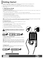
The KPX-7V2 Keypad has a special Channel 0 feature which allows the
Keypad to transmit without the user having to enter a PIN. It is intended
to be
used for non-secure functions
such as a door bell, pedestrian
access, lighting, etc. Simply pressing and holding the ‘0’ button for
more than 0.5 second will cause the Keypad to transmit the function
coded on Channel 0 button.
As an example to code the Channel 0 to operate the door bell you
need a FHCRX-1 receiver (available to purchase from dealer) which is
connected to your doorbell. Then follow instructions in Section 3.2
Coding KPX-7V2 to other Receivers.
NOTE: Skip the User Pin in step 3.2c.
3.2 Coding KPX-7V2 into the other Receivers
The KPX-7V2 Keypad can operate other functions such as; door bells, automatic gates, external lighting, etc. as long as each functional
product is connected to an Automatic Technology Receiver (available to purchase from dealer) The receiver needs to learn the codes of any
keypad / transmitter that will be used by the operator.
a. Decide which Channel button (eg. 2 = Automatic Gate, 3 = Outside light) is to be used to operate your desired function.
b. Code the Channel button to the operator’s receiver by pressing and holding the coding button** on the Receiver.
c. Enter in your User Pin Code and select the chosen Channel button and hold for 2 seconds.
d. Release the Channel button and pause for 2 seconds.
e. Select the same Channel button and hold for 2 seconds.
f. Release both the Channel button and the coding button on the Receiver.
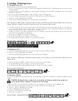
**: The coding button to code the KPX-7V2 into the receiver is different depending on the receiver. For Example:
Door Code =
Garage Door Opener
SW1 =
FHCRX-1 / FHRX receiver
Logic console, DCB-05 and NeoSlider = See below 3.3
NOTE:
When coding the Channel 0 button, skip entering the User Pin in step 3.2c and continue by pressing the 0 button and holding for
2 seconds.
3.3 Coding KPX-7V2 into Logic Console, DCB-05 and NeoSlider
The Logic Console, DCB-05 and NeoSlider all have LCD screens to display prompts. To code the KPX-7V2 keypad into the device;
a. Press NEXT on the device to navigate to Menu 1 (Coding Transmitters)
b. Press SET to enter code set procedure.
c. The device will beep and prompt to press one of the keypad / transmitter buttons.
d. Decide which Channel button (eg. 2 - Automatic Gate) on the keypad is to be used to operate your desired function.
e. Enter in your User Pin Code and select the chosen Channel button and hold for 2 seconds.
f. Release the Channel button and pause for 2 seconds.
g. Select the same Channel button, hold for 2 seconds and release.
h. The device will now show the transmitter’s record, with a cursor on the field for the button being coded. Use the UP/DOWN buttons to
select the function for the button.
i. Press SET to save the settings.
FHCRX-1
4. Mounting and Maintenance
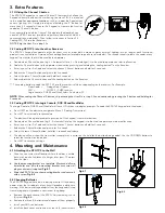
4.1 Attaching the KPX-7V2 to the Wall
a. Choose a convenient wall location where the door is visible,
but out of reach of children at a height of at least 1.5meters
from the floor.
b. Use the mounting bracket as a template. Mark and drill two
6mm holes and affix the mounting bracket with two wall
plugs and screws (supplied)
Fig 4.1
.
c. Slide the KPX-7V2 on to the mounting bracket and secure it
with a screw
Fig 4.2
.
4.2 Changing Batteries
The KPX-7V2 Keypad has a built-in battery monitor. If the battery
power is low, the first depress of any key will produce a distinctive
warning. If the battery voltage drops further, the keypad will stop
transmitting and will produce a continuous long beep.
Fig 4.1
Fig 4.2
a. Remove the back cover of the KPX-7V2 by removing the six
(6) screws
Fig 4.3.
b. Remove the three (3) batteries and dispose of them properly.
c. Install new AAA size batteries.
d. Install the back cover and secure with the six (6) cover screws.
Fig 4.3