background image


Owner Installation Instructions 

Axess® Pro Series 3100

15

To Desired

CLOSE Limit, 

SET

To Desired

OPEN Limit, 

SET

17

fi g

16

fi g

Setting Limits via Logic Console

Step 7 - Setting Travel Limits 

Turn on the power to the opener. The controller will  
go through a start up sequence. 
After a short delay the MAIN SCREEN 

(Fig. 16)

 will 

be displayed. If this is the fi rst time the Axess® Pro 
Series 3300 is being used, the MAIN SCREEN should 
enter into limit set mode and the blue close LED 
will be fl ashing. If the display shows that an input is 
active, then rectify the situation before continuing 
with the procedure for setting the travel limits. Press 
and hold the CLOSE button - the shutter should start 
closing.

If the shutter opens, release the CLOSE 
button and press the STOP button once 
to change the motor’s direction. Press and 
hold the CLOSE button until close position 
of the shutter is reached.
If the shutter overshoots, press the OPEN 
button to move the shutter in the open 
direction. 

When the shutter is at the desired close position, press 
the SET button to record the close limit position. The 
display will change and the green open LED will start 
to fl ash 

(Fig. 17)

.

Press and hold the OPEN button to open the shutter. 
When the shutter is at the desired open position, 
release the OPEN button

If the shutter overshoots, press the CLOSE 
button to move the shutter in the CLOSE 
direction.

WARNING! 

Once the next step is performed, the 

shutter will automatically close and open to calculate 
travel time settings. Keep persons and objects clear of 

the shutter.

Press the SET button to store the open limit. The 
shutter will now automatically close and open to 
calculate the travel time settings. After this, If PE Beams 
are installed, the opener can be operated with the 
OPEN or CLOSE button on the logic console or from 
the transmitter. Otherwise, the controller will be loaded 
with “Safety Close Mode.” (Page 28)

1.

2.

»

»

3.

4.

»

5.

Summary of Contents for Axess Pro 3100

Page 1: ...ess Pro Series 3100 Industrial Roller Shutter Opener Featuring TrioCode Technology INSTALLATION INSTRUCTIONS OWNERS COPY Technical Document Installation Manual v1 11 14 Dec 2011 English Part 13296 Manual ...

Page 2: ...r directly or indirectly from failure to install the Automatic Technology Australia industrial roller shutter opener in accordance with these installation instructions WARNING Electrical wiring must be in compliance with your local building and electrical codes WARNING It is vital for the safety of persons to follow all instructions Failuretocomplywiththeinstallationinstructions and the safety war...

Page 3: ...ation 14 Viewing And Editing Parameters 15 Setting Limits with Logic Console 16 Setting Limits Via Transmitter 17 Menu Structure 18 Coding Transmitters 19 Transmitter Editing 20 Transmitter Management 22 Remotely Coding Transmitters 24 Setting Pedestrian Position 25 Reprofiling The Shutter Travel 25 Control Board Adjustments 26 Current Trips 26 Auto Close Times 26 Light Times 27 Motor Settings 28 T...

Page 4: ...smitter storage and names setting various parameters selecting specialised operating modes and performing system diagnostics Status Indication The status of the opener can be determined at anytime by observing the console s LCD screen When the MAIN SCREEN is displayed the current position of the shutter or the result of the last movement can be found The display will also show the count down progr...

Page 5: ...light relay module The light relay module can control the warning or courtesy light The timing of these outputs can be adjusted to suit your needs Extensive Operating Modes Via Control Inputs And Remote Control The integrated controller can be configured to operate in many different ways via its 7 control and safety inputs These include P E FIRE GPI OPEN STOP CLOSE and SWIPE Remote control operatio...

Page 6: ...wiring must be compliance with your local building and electrical codes The shutter must be well balanced and in good working order Shutter springs brackets and their hardware are under extreme tension and can cause serious personal injury Do not attempt to adjust them A faulty shutter must be repaired by a industrial roller shutter professional prior to opener installation Remove or disengage all...

Page 7: ...t Drive Shaft Assembly 1 Chain 10B 0 625 1 Sprocket 14T 0 625 1 Mounting Flange 1 Ax30 Fastener Pack 1 TrioCode Keyring Transmitters 2 EasyBeam with wires and brackets 1 Installation Manual 1 Logic Console Transmitters EasyBeam Communication Cable Timing assembly Chain 10B M ounting Flange Output Drive Shaft 14T Sprocket Ax30 Fastener Pack Not available with some models Manual Console Power Drive ...

Page 8: ...al interface connector Position sensor connector 10 Amps slow blow mains fuse 03 04 02 01 05 01 02 03 04 05 02 fig WARNING HIGH VOLTAGE This unit is not user serviceable Disconnect power supply before removing cover Please ensure all electrical cables are secured clear of any moving parts Failure to comply may cause electrocution resulting in serious injury or death ...

Page 9: ...uxiliary Output FIRE Input Terminal N O or N C GPI N O Input Terminal N O OPN Input Terminal N O or N C STP Input Terminal N O or N C CLS Input Terminal N O SWP Input Terminal N O COM Terminal For Inputs Programmer PG 3 Input Console Previous Button Liquid Crystal Display Console Next Button Console Open Button Console Stop Button Console Set Button Console Close Button RJ45 Connector 06 07 08 09 ...

Page 10: ...d clearance needs to be at least 150mm Step 2 Drive Unit Pre assembly The opener can be installed on either the right or left hand side of the shutter when viewed from inside the building The timing assembly mounting flange and drive shaft needs to be assembled according to the installation side Assembling the opener for RIGHT HAND installation is explainedbelow ForLEFT HANDsideinstallation assembl...

Page 11: ...quired and fix ends to make a loop NOTE Ensure that hand chain is not twisted when making a loop WARNING Do not turn the power on to the opener before connecting either console Step 4 Installing The Logic Or Manual Console Remove the main cover Affix the logic or manual console at a height of 1 5 metres within sight of the shutter Make sure that the position of the logic or manual console is out of ...

Page 12: ...the shutter overshoots press the OPEN button to move the shutter in the open direction When the shutter is at the desired close position press the SET button to record the close limit position The green open LED will start to flash Press and hold the OPEN button Fig 10 to open the shutter When the shutter is at the desired open position release the OPEN button If the shutter overshoots press the CL...

Page 13: ...Beam in a strategic location in the doorway Automatic Technology recommends that the sensor is placed 100mm above the floor level and as close as possible to the shutter opening Connect as per the wiring diagram Fig 13 Step 6 2 Alignment Power up the Axess Pro Series 3300 with the EasyBeam connected The green LED on the transmitter should turn ON to indicate power is present If the receiver is conn...

Page 14: ...down causes the parameter s value to change rapidly The longer the button is held the faster the value changes Press SET to SAVE the setting Reload Default Setting Press NEXT PREV buttons to display the LOAD DEFAULT screen Press SET to load the default value Return To Menu If the parameter s value is not to be changed press STOP to return to the sub menu Press STOP again to return to the MAIN SCRE...

Page 15: ... position of the shutter is reached If the shutter overshoots press the OPEN button to move the shutter in the open direction When the shutter is at the desired close position press the SET button to record the close limit position The display will change and the green open LED will start to flash Fig 17 Press and hold the OPEN button to open the shutter When the shutter is at the desired open posi...

Page 16: ...dure The close blue LED will start to flash Step 8 4 Setting Limits Via Transmitter Press and hold Button 4 on the transmitter to close the shutter If the shutter opens release button 4 and press the STOP button once on the logic console to change the direction of the motor Then press and hold Button 4 on the transmitter to close the shutter If the shutter is closed too far press Button 1 to inch t...

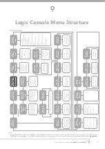
Page 17: ...page 33 Event history display See page 33 Periodic service cycle counter See page 34 View Parameters See page 34 Memory usage See page 33 Parameter list 1 Open speed frequency 2 Close speed frequency See page 27 See page 27 NOTES 1 Press PREV NEXT buttons move to Left Right 2 Press OPEN CLOSE buttons to change setting 3 Press SET button to save changes 4 Press STOP to return to MENU without saving...

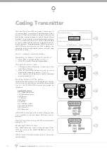
Page 18: ...s the same transmitter button again as prompted by the display Fig 23 Selecting Function Of The Button The logic console will now show the transmitter s record with a cursor on the field for the button being coded Fig 24 Use OPEN CLOSE to select the function for the button Available functions OSC Open Stop Close PED Pedestrian access SWP Swipe CLS Close OPN Open STP Stop LGT Courtesy Light VAC Vaca...

Page 19: ...EN or CLOSE to change the displayed value Fig 27 The available functions are shown below Selecting OFF will prevent the opener responding to that button Available functions OSC Open Stop Close PED Pedestrian access SWP Swipe CLS Close OPN Open STP Stop LGT Courtesy Light VAC Vacation Mode AUX Auxiliary OFF No action NOTE OSC will change to OS and CLS Close function is not available in the case whe...

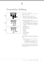
Page 20: ...V to move the cursor over the ID field Press NEXT to reveal the Serial Number Fig 31 The serial number display is provided for additional means of identification The transmitter in this example has serial number 12345 Editing A Character Field Press NEXT or PREV to move the cursor Fig 32 Press UP or DOWN to scroll through and select a new character Press NEXT or PREV to move the cursor to the next c...

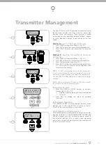
Page 21: ...er parameters Fig 36 This method is used for quick navigation if the transmitter is available NOTE VIEW will not be shown if the transmitter is not stored Once the list is displayed it can be sorted by stored number ID Label or Serial Number Use the NEXT or PREV buttons to select the sorting method NOTE When sorting by ID label or S N only stored transmitters locations are displayed Navigating The...

Page 22: ...ransmitter from memory along with the name and button function settings Edit Operation The edit operation displays the transmitter record for editing purposes See Transmitter Editing page 20 Copy Operation Thecopyoperationisusedtocodemultipletransmitterswith the same button function as that of the selected transmitter Once selected an abbreviated code set routine is initiated which repeats steps 1...

Page 23: ... OPN wait for the shutter to complete its cycle Step 11 3 Activate Remote Code Set Mode Use a small pin to press and hold through the Coding button Hole of the existing transmitter for 2 seconds Fig 43 Step 11 4 Code New Transmitter Button Within 10 seconds press the button on the new transmitter you wish to code for 2 seconds Fig 44 Step 11 5 Confirm The Transmitter Button To Be Coded Press the sa...

Page 24: ...ave the Pedestrian Access position Fig 45 Press the STOP button to exit to the main screen Step 12 2 Checking Pedestrian Position When activated by a transmitter button which is coded as PED mode the opener drives the shutter to the preset position from either above or below PED Mode s active status is indicated on the display Fig 46 If a PED Mode button is pressed while the shutter is moving the ...

Page 25: ...cteristics of the shutter change due to mechanical adjustments etc To initiate a re profile locate MENU 10 2 Reprofile Travel Press SET and follow the prompts The shutter will start to move and re calculate force margins The shutter can move between the open and close limit positions up to two 2 times depending on the position of the shutter and the power up condition A single beep will be heard onc...

Page 26: ...se This mode is selected by entering a non zero time for the P E Auto Close parameter This mode is used to Auto Close the shutter but only after a vehicle has passed through the doorway and triggered the P E input The swipe input can be used to clear the P E triggered status so that the P E input must be activated again before the countdown will start As with the other P E modes the STP input will...

Page 27: ...in Menu 7 Operating Modes must be selected ON and also sub menu 4 OPN I P N C operation in Menu 7 Operating Modes must be selected ON This mode is used to Auto Close the shutter only after a vehicle has passed through the doorway to exit the premises The 2nd P E OPN input must be active when the P E input is activated in order for a P E triggered Auto Close to be activated 3 wire P E BEAM recommen...

Page 28: ... MODE has been enabled as no P E Beam has been installed This means that the shutter can only be closed by HOLDING the CLS input or CLOSE button All other means of closing the door are disabled Press SET to continue Menu 6 2 P E Beams Input Response Mode The P E Beam s input can be configured to respond in one of three modes Reverses Close Cycles In this mode the P E Beams input has no effect when ...

Page 29: ...cond P E Beams Input Selecting this parameter will allow the OPN input to be used as a second P E Beams input When the OPN input is active the shutter is prevented from being closed If the OPN input is triggered while the shutter is closing the logic console will stop the motor and then open the shutter The OPN input has no effect while the shutter is opening The second P E Beam OPN input must be ...

Page 30: ...e is turned on the User is requested to enter the desired password to be used The password protection feature has a time out that expires after 60 seconds of inactivity Alternatively the User may log out manually by pressing exit when the main screen is displayed PG3 can disable the password Menu 6 17 Transmitter Grouping The transmitter store number display format can be changed to show a grouped...

Page 31: ...8 STP INPUT N C OPERATION Selects operating polarity of STP input Off On Off 6 9 FIRE INPUT N C OPERATION Selects operating polarity of FIRE input Off On Off 6 10 FIRE INPUT MODE configure the fire input Options are OPN CLS and PED OPN CLS PED OPN 6 11 REMOTE CODE ENABLED Selects remote transmitter coding function Off On On 6 12 ACTIVITY REPORTS Select report to be output Off 255 Off 1 6 13 ACTIVITY...

Page 32: ... displayed and set Fig 48 NOTE The time is in a 24 hour format and the Day of the week is not automatically set with the date To change the settings simply press UP or DOWN to display the cursor and then move to the field to be changed using the NEXT PREV buttons Then press OPEN CLOSE to change the setting and then the SET or STOP buttons to save Menu 7 2 View Programs Select this menu to display o...

Page 33: ...s menu three sub menus are available Run Programs The programs of the timer can be interrupted by selecting RUN PROGRAM off Configuration Of GPI Input General Purpose Input can be configured as OSC PED or DST setup This is activated by the GPI input terminal with the N O switch When GPI Selected As OSC If the shutter is moving the activation of the GPI input or pressing a transmitter button with the...

Page 34: ...opener will then beep each time a transmission is received If the transmitter button is stored in the controller memory and has a function assigned to it a second screen will be displayed showing the transmitter details along with the button pressed Fig 54 The example shows the case where transmitter number 14 is activated by button 4 Note ID is selected for display Menu 8 3 Display History The op...

Page 35: ...en Cycles 2 Close Cycles 3 PED Cycles 4 Setup Limits 5 Warranty Cycles 6 Open O LS 7 Close O LS 8 Open Stalls 9 Close Stalls 10 Direction Faults 11 Position Sensor faults 12 Drive Memory Faults 13 Position Wrap Faults 14 Console Volt Faults 15 PCB Temp Fault 16 Comms Compat Faults 17 INV logic faults 18 Low DC Bus Volt Faults Menu 8 7 Install Data Open Position Shows the fully open position shutte...

Page 36: ...memory Once selected the PREV or NEXT buttons can be used to view the Memory Tool options To execute the displayed option simply press SET Menu 9 1 Clear Control This option will clear the shutter control memory and reload the factory set defaults for parameters such as the lock time light time Auto Close times etc It will also clear the travel limits Menu 9 2 Clear Tx ers This option will clear t...

Page 37: ...Transmitter Codes Receiver Sensitivity 103 dB Transmitter frequency UHF Multi frequency FM Transmitter Coding type Code hopping Number of code combinations Over 4 29 billion random codes Code generation Non linear encryption algorithm Courtesy light Common Collector Transistor output Controller fuse 10A slow blow Transmitter Battery CR 2032 3 Volts Real Time Clock Battery CR 1220 1 5 Volts NOTE 1 ...

Page 38: ...sole OPEN CLOSE button but not from transmitter Transmitter code not stored in memory Code transmitter into opener s memory Transmitters operation disabled from the time clock Enable the transmitter operation in the time clock menu The opener is in Vacation Mode Turn off Vacation Mode Flat battery Replace battery Shutter does not close with transmitter Safety Close Mode is on Turn the Safety Close...

Page 39: ...te smoothly call your industrial roller shutter professional Yearly Automatic Technology suggests you contact your industrial roller shutter professional to perform an annual shutter service CAUTION Frequently examine the shutter particularly springs and mountings for signs of wear damage or imbalance Do not use if repair or adjustment is needed since a fault in the installation or an incorrectly ...

Page 40: ...40 Axess Pro Series 3100 Owner Installation Instructions Spare Parts ...

Page 41: ...e product and subject to paragraph 1 above all warranties of whatsoever kind relating to the product are hereby excluded 10 This Warranty excludes damage resulting from a normal wear and tear b accidental damage c incorrect installation of the Product d blown fuses electrical surges power surges or power spikes e theft fire flood rain water lightning storms or any other acts of God f any installatio...

Page 42: ... of Automatic Technology Australia Pty Ltd No part of this document may be reproduced without prior permission In an ongoing commitment to product quality we reserve the right to change specification without notice E OE Automatic Technololgy Australia Pty Ltd ABN 11 007 125 368 6 8 Fiveways Boulevard Keysborough Victoria 3173 Australia P 1300 133 944 61 3 9791 0200 International Enquiries Only E sa...

Reviews: