background image

 ST3000 Autopilot

6    ST3000 Autopilot Service Manual   83004-2

Chapter 4. Disassembly/Assembly
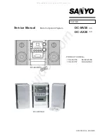
SeaTalk Deck Plug

Screw (x2)

Pin carrier

Plug pin screw (x3)

Plug pin (x3)

Metal sleeve (x3)

Brown wire

Blue wire

Yellow
wire

Plug body

Cable
clamp

Cable
seal

Clamp
nut

Cable assembly
(3016-104)

D4107-1

Assemble sleeve to wire. 
Pinch sleeve with pliers. Insert
sleeve into plug pin and tighten 
screw to retain. Cut off excess 
metal sleeve to prevent short 
circuit.
Repeat process for remaining 
wires.

Electrical connections

Wire colour

Description

Brown

+12V nominal supply

Blue

0V supply

ST3000 Autopilot Display Unit

Spare parts list

The item numbers refer to Figure 2: ST3000 Autopilot display unit.

Item

Spare Description

Part No.

Comments

Control Head

Q056

Complete head

LCD kit, 

including

Q053

4

LCD surround

5

LCD

6

Elastomer

7

Diffuser

8

Reflector

27

Locking wedge (x5)

9

PCB assembly

Q044

LCD not included

13

Fluxgate assembly

M022

30

SeaTalk deck plug assembly

D326

Summary of Contents for ST3000

Page 1: ...t by any means of parts or components not supplied for or not approved for such use by Raytheonor ifsuppliedorapprovedforusebyRaytheon notproperlyfittedinaccordancewithinstructionspublished providedorrecommendedbyRaytheon maycausetheequipmenttomalfunctionand inparticular tobecomeunsafeor tonolongermeettherelevantCErequirements Inthesecircumstances RaytheonMarineEuropeLtdexcludesliability to the fu...

Page 2: ...nstallation with the drive unit facing forward requires resetting To reset the operating sense press the 1 and 1 course keys together for 5 seconds The unit beeps for 10 seconds to confirm changeover and the display shows the new setting either Port actuator sprocket facing forward or Starb actuator sprocket facing aft The autopilot may be calibrated t to suit a particular vessel Note the calibrat...

Page 3: ...e correct pilot type using the 1 and 1 degree keys 4 Save the setting by pressing the 10 and 1 degree keys until the normal Standby display appears Approximately 2 seconds Note Changing Autopilot type will clear all calibration settings Display of software code The software code of the pilot can be displayed as follows 1 Switch the pilot to standby mode 2 Press the Standby key until the display sh...

Page 4: ...old 10 key Check motor runs OK No Yes Press Hold 10 key Check actuator runs Disconnect power and remove drive module Disconnect motor spade terminals and apply 10V DC to motor terminals Check motor runs See Figure 3 OK Press AUTO and check display shows A followed by a heading OK Change PCB Restart OK No Yes Change motor Restart No Yes OK Hold unit vertical rotate it an anti clockwise direction ch...

Page 5: ...ompass assembly Remove the fluxgate assembly see Figure 2 The compass can be checked with a DVM as follows Connectmeteracross Resistance 1 and 2 10ohms 3 and 5 5 ohms 3 and 4 5 ohms 1 and 3 Opencircuit D4104 1 1 2 3 4 5 No connection Figure1 Fluxgateelectricalconnections ...

Page 6: ...d tighten screw to retain Cut off excess metal sleeve to prevent short circuit Repeat process for remaining wires Electrical connections Wirecolour Description Brown 12Vnominalsupply Blue 0Vsupply ST3000 Autopilot Display Unit Spare parts list The item numbers refer to Figure 2 ST3000 Autopilot display unit Item SpareDescription PartNo Comments ControlHead Q056 Completehead LCDkit including Q053 4...

Page 7: ...x6 3 Actuator x6 4 LCD surround 5 LCD 6 Elastomer connector 7 Diffuser 8 Reflector 9 PCB 10 Seal 11 Gimbol support x2 12 Gimbol support screw x2 13 Fluxgate assembly 14 Rear case 15 Case screw x4 16 Fluxgate ground Insert wedge 27 as shown to secure display bezel leg Wedge 27 PCB 9 Display bezel 4 Early units Later units Important The fluxgate loom in some early units is wired differently 17 Fluxg...

Page 8: ...ctuator Item SpareDescription PartNo Comments ST3000drivemodule Q45 Completedrive ST3000Gearbox Drive assembly including Q102 1 Pin 2 Clutchflange 3 Gearboxhousing 4 Seal 2 1 Clutchflange pin H006 AlsopartofQ102 7 Motor Q101 10 Pod H001 Motor replacement If the gearbox is noisy when the motor is replaced remove motor rotate gearbox a small amount and refit ...

Page 9: ...3 14 1 Pin 2 Clutch flange 3 Gearbox housing 4 Seal 5 Flux ring 6 Location screw 7 Drive motor 8 Cap 9 Seal 10 Pod 11 Shroud 12 Grip 13 Seal 14 Location ring 15 Receptacle 16 Socket 17 O ring Note Connect a 10v dc supply to the actuator plug and measure the running current of the drive unit 2A Drive healthy 2A Drive faulty Figure3 ST3000DriveActuator ...

Page 10: ...ST3000 Autopilot 10 ST3000 Autopilot Service Manual 83004 2 Chapter 5 PCB Details D4108 1 Figure4 CircuitDiagram ...

Page 11: ...ST3000 Autopilot ST3000 Autopilot Service Manual 83004 2 11 PCB Layout D4105 1 Taken from Drawing No 4155 010 Issue J Date 07 03 97 Figure5 PCBComponentLayout ...

Page 12: ...m Drawing No 4155 010 Issue J Date 07 03 97 Raytheon Marine Company 676 Island Pond Road Manchester New Hampshire 03109 5420 Tel 001 603 647 7530 Fax 001 603 634 4756 Raytheon Marine Europe Limited Anchorage Park Portsmouth Hampshire PO3 5TD Tel 01705 693611 Fax 01705 694642 http www raytheon com ...

Reviews: